
Specifications


CINTERION
®
BGS12 Hardware Interface Description
Contents
37 of 109
Page
BGS12 HID_V00.915
Confidential / Released
2019
-
01
-
07
3.4.5 Timing of the CTS Signal in CYCLIC SLEEP Modes
The CTS signal is enabled in synchrony with the module’s paging cycle. It goes active low each
time when the module starts listening to a paging message block from the base station. The
timing of the paging cycle varies with the base station. The duration of a paging interval can be
calculated from the following formula:
4.616 ms (TDMA frame duration) * 51 (number of frames) * DRX value.
DRX (Discontinuous Reception) is a value from 2 to 9, resulting in paging intervals from 0.47
to 2.12 seconds. The DRX value of the base station is assigned by the network operator.
Each listening period causes the CTS signal to go active low: If DRX is 2, the CTS signal is
activated every 0.47 seconds, if DRX is 3, the CTS signal is activated every 0.71 seconds and
if DRX is 9, the CTS signal is activated every 2.1 seconds.
The CTS signal is active low for 5ms. This is followed by another 5ms UART activity. If the start
bit of a received character is detected within these 10ms, CTS will be activated and the pro-
per reception of the character will be guaranteed. CTS will also be activated if any character is
to be sent.
After the last character was sent or received the interface will remain active for
•
another 2 seconds, if AT+CFUN=7
•
or for an individual time defined with AT^SCFG, if AT+CFUN=9. Assertion of RTS has the
same effect.
In the pauses between listening to paging messages, while CTS is high, the module resumes
power saving and the AT interface is not accessible. See Figure 10 and Figure 11.
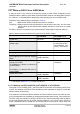
Figure 10: Timing of CTS signal (example for a 2.12 s paging cycle)
Figure 11 illustrates the CFUN=7 modes, which reset the CTS signal 2 seconds after the last
character was sent or received.