
Specifications


CINTERION
®
BGS12 Hardware Interface Description
Contents
30 of 109
Page
BGS12 HID_V00.915
Confidential / Released
2019
-
01
-
07
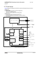
reset state. The reset state is described in Section 3.3.3 as well as in the figures showing the
startup behavior of an interface.
After releasing the EMERG_RST line, i.e., with a change of the signal level from low to high,
the module restarts. The other signals continue from their reset state as the module was
switched on by the ON signal.
Figure 8: Emergency shutdown/restart timing
It is recommended to control this EMERG_RST line with an open collector transistor or an open
drain field-effect transistor.
Caution: Use the EMERG_RST line only when, due to serious problems, the software
is not responding for more than 5 seconds. Pulling the EMERG_RST line causes the
loss of all information stored in the volatile memory. Therefore, this procedure is intend-
ed only for use in case of emergency, e.g. if BGS12 does not respond, if reset or
shutdown via AT command fails.
3.3.3 Signal States after Startup
Table 7 lists three states each interface signal passes through during reset and firmware in-
itialization:
1) At reset: BGS12 begins to startup and performs the reset action.