
Specifications


CINTERION
®
BGS12 Hardware Interface Description
Contents
26 of 109
Page
BGS12 HID_V00.915
Confidential / Released
2019
-
01
-
07
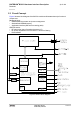
3.2.2 Measuring the Supply Voltage (V
BATT+
)
To measure the supply voltage V
BATT+
it is possible to define two reference points GND and
BATT+. GND should be the module’s shielding, while BATT+ should be a test pad on the
external application the module is mounted on. The external BATT+ reference point has to be
connected to and positioned close to the SMT application interface’s BATT+ pads 5 or 53 as
shown in Figure 4.
Figure 4: Position of reference points BATT+ and GND
3.2.3 Monitoring Power Supply by AT Command
To monitor the supply voltage you can also use the AT^SBV command which returns the value
related to the reference points BATT+ and GND.
The module continuously measures the voltage at intervals. The displayed voltage (in mV) is
averaged over the last measuring period before the AT^SBV command was executed.
If the measured average voltage drops below or rises above the specified voltage shutdown
thresholds, the module will send an "^SBC" URC and shut down. (for details see Section
3.3.5)
3.3 Power Up/Power down Scenarios
In general, be sure not to turn on BGS12 while it is beyond the safety limits of voltage and tem-
perature stated in Chapter 5. BGS12 will immediately switch off after having started and de-
tected these inappropriate conditions. In extreme cases this can cause permanent damage to
the module.
3.3.1 Turn on BGS12
BGS12 can be started as described in the following sections:
Hardware driven switch on by ON line: Starts Normal mode (see Section 3.3.1.1).
3.3.1.1
Switch on BGS12 Using ON Signal