
User manual


2.0 INSTALLATION GUIDELINES
R599791 - FORCE 3D User Manual 15
2.11 Advanced Optical Alignment
Boresight Alignment Procedure
1) Display the Boresight Test Pattern by pressing the TEST key on the remote keypad or use the built-in keypad
and press the soft key that displays Test on the LCD display, then UP ARROW KEY to cycle to Boresight, then
Enter, to obtain the Boresight pattern below.
Boresight pattern.
2) Focus the image on cross-hair pattern I. Evaluate the focus on cross-hair image II and III. If all 3 images are in
focus, no further action is required. If boresight is required see step 3.
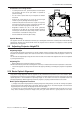
3) If boresight is required, use a 5mm Allen™ key to loosen the 3 locking setscrews on the lens mount, see figure
below.
Cap screws (A) and Setscrews (B) location.
4) Fine tune the focus of cross-hair pattern I by adjusting the corresponding capscrew. See screw locations
above. Adjust until the cross-hair image in pattern I is in focus with minimal flare.
5) Repeat the adjustment for pattern II.
6) Repeat the adjustment for pattern III.
7) Repeat step 4, 5, and 6 as required until all 3 cross-hair patterns are in equal sharp focus. If the boresight is
acceptable, see step 10. If the boresight does not appear to be converging to an acceptable level of image quality
The setscrews must be backed out several turns, so that they do not contact the inner lens mount plate.
Pattern I Pattern II
Pattern III
A
B
A
B
A
B