
Installation Guide

738T WIRELESS TRANSLATOR
Installation Guide
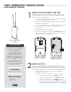
Figure 1: 738T Wireless
Translator
DESCRIPTION
1
The 738T Wireless Translator allows
technicians to convert systems with
existing, one way, low frequency,
wireless transmitters.
The 738T is compatible with
transmitters that operate at
319.5 (GE Interlogix) or 345 MHz
(Honeywell 5800 Series Wireless)
and can be wired directly to the
keypad bus of an XT30/XT50 Series
panel.
Transmitters that have been
learned into the 738T are able to
send supervision and low battery
messages to the panel.
Compatibility
DMP XT30/XT50 Series panels
What is Included?
• 738T Wireless Translator
• Antennas (2)
• Hardware Pack
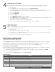
MOUNT AND ASSEMBLE THE 738T
Mount the 738T Wireless Translator in a central location to the
system’s wireless sensors. Keep in mind, the translator must be
wired to the panel’s keypad bus.
1. Open the 738T housing by pushing the tabs at the bottom
of the device and lifting the cover o.
2. Remove the PCB by dis-engaging the PCB clips and lifting
the PCB out of the base.
3. Use the included screws in the mounting hole locations to
secure the 738T to the wall or other flat surface.
See Figure 2.
4. Snap the PCB back in to the base.
5. Insert the included antennas into the Antenna terminals at
the top of the PCB. See Figure 3. Tighten the screws until
the antennas are secured in place.
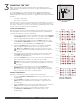
Figure 2: Mounting Holes
8 4 2
1
4
2
1
Forward
Backward
Enter
Status
Address Zone
Bus
UC
RX
TX
Freq
BLK
GRN
YEL
RED
Figure 3: PCB Features and
Wiring Connections
Use 18 to 22 gauge wire to connect the 738T directly to the
keypad bus of an XT30/XT50 Series panel. This connection allows
the translator to communicate with the panel and receive 12VDC
power. DMP recommends a 2,500 foot maximum wiring distance.
1. At the panel, connect the wires to the corresponding
keypad bus terminals.
2. Connect the wires to the 738T’s terminals. See Figure 3.
a. Connect the red wire to the +12(R) terminal.
b. Connect the yellow wire to the OUT(Y) terminal.
c. Connect the green wire to the IN(G) terminal.
d. Connect the black wire to the GND(B) terminal while
pressing the Enter button. See Figure 4. This clears
the 738T’s memory and prepares it for programming.
WIRE THE 738T
2