
User guide


20833-01 Rev 04
Page 7-1
7 TRANSMITTER FUNCTIONS
Table of Contents
7 TRANSMITTER FUNCTIONS ......................................................................................... 7-1
7.1 Introduction .............................................................................................................. 7-3
7.2 Transmitter Layout ................................................................................................... 7-3
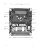
7.2.1 Transmitters With Non-Pluggable Terminal Blocks .......................................... 7-4
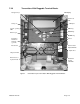
7.2.2 Transmitters With Pluggable Terminal Blocks .................................................. 7-5
7.3 Transmitter Output Definitions ................................................................................. 7-6
7.3.1 COMM ............................................................................................................. 7-7
7.3.1.1 MODBUS ................................................................................................. 7-7
7.3.2 PULSE ............................................................................................................. 7-7
7.3.3 ALARM ............................................................................................................ 7-8
7.3.3.1 External Alarm Circuits: ............................................................................ 7-9
7.3.4 CUR1 (Primary 4-20mA Output) .................................................................... 7-10
7.3.5 CUR2 (Secondary 4-20mA Output) ................................................................ 7-10
7.3.5.1 Internally Powered 4-20mA Loop Configuration ..................................... 7-10
7.3.5.2 Externally Powered 4-20mA Loop Configuration .................................... 7-11
7.3.6 SHD ............................................................................................................... 7-11
7.3.7 Fieldbus ......................................................................................................... 7-11
7.4 Transmitter Input Definitions .................................................................................. 7-12
7.5 Keypad .................................................................................................................. 7-13
7.6 Transmitter Display ................................................................................................ 7-14
7.6.1 Operational Mode .......................................................................................... 7-14
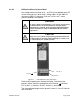
7.6.1.1 System Start .......................................................................................... 7-14
7.6.1.2 Operating Transmitter Display ................................................................ 7-15
7.6.1.2.1 Line 1 / Line 2 ..................................................................................... 7-15
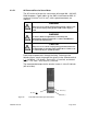
7.6.1.2.2 Status Line .......................................................................................... 7-16
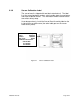
7.6.1.3 Display Examples ................................................................................... 7-18
7.6.2 Menu Mode .................................................................................................... 7-19
List of Figures
Figure 1 Transmitter Layout: Transmitters With Non-Pluggable Terminal Blocks ............... 7-4
Figure 2 Transmitter Layout: Transmitters With Pluggable Terminal Blocks....................... 7-5
Figure 3 Transmitter Output Terminals: Transmitters With Non-Pluggable
Terminal Blocks ...................................................................................................................... 7-6
Figure 4 Transmitter Output Terminals: Transmitters With Pluggable Terminal Blocks ...... 7-6
Figure 5 Pulse Switch Closure ........................................................................................... 7-8
Figure 6 Alarm Switch Closure........................................................................................... 7-8
Figure 7 Example Alarm Circuit Diagram With Load 100mA Maximum .............................. 7-9
Figure 8 Example Alarm Circuit Diagram With Load Greater Than 100mA ........................ 7-9
Figure 9 Internally (Transmitter) Powered 4–20mA Loop ................................................. 7-10
Figure 10 Externally Powered 4–20mA Loop ................................................................. 7-11
Figure 11 Transmitter Sensor Terminals ........................................................................ 7-12
Figure 12 Transmitter Front Panel Keyboard ................................................................. 7-13
Figure 13 Startup Screen ............................................................................................... 7-14
Figure 14 Operating Transmitter Display........................................................................ 7-15
Figure 15 Flow Rate Is Less Than Minimum Configuration ............................................ 7-18