
User guide

20832-01 Rev 05
Page 6-16
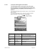
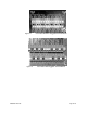
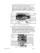
6.3.4.4 Transmitter Input Connections (Section #2)
In some cases, a pressure or temperature transducer signal is used
as an input to the transmitter (currently not used for VF-100 system).
These terminals are shown in the following figures.
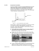
The transducers must be 2-wire loop-powered 4-20mA current
transmitters. The 2 wires must be “floating” (i.e. not ground-
referenced) for safety reasons and because they are powered from +/-
12V from the Transmitter.
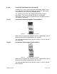
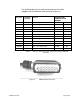
6.3.4.4.1 Transmitters With Non-Pluggable Terminal Blocks
Figure 10 Transmitter Sensor Terminals
When used, the setup of the individual sensors is performed as part of
the overall transmitter setup detailed in this manual.
The recommended torque for the terminal screws is 4.4 to 5.3 lb
f
-inch
(0.5 to 0.6 Nm).
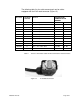
6.3.4.4.2 Transmitters With Pluggable Terminal Blocks
Figure 11 Transmitter Sensor Terminals
When used, the setup of the individual sensors is performed as part of
the overall transmitter setup detailed in this manual.
The recommended torque for the terminal screws is 4.4 to 5.3 lb
f
-inch
(0.5 to 0.6 Nm).