
User guide

20832-01 Rev 05
Page 6-12
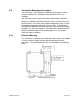
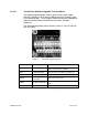
6.3.4.2 Transmitters With Pluggable Terminal Blocks
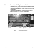
The following figure shows the layout of the transmitter terminal strip
board. This board is divided into three sections.
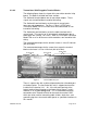
The Section#1 terminal blocks are for transmitter outputs. These
signals are not certified Non-incendive field wiring.
The Section #2 terminal blocks are for external sensor inputs
(pressure and temperature). For Class I, Zone 2, ATEX rated
Transmitter Model TB8-xx-xx-xx-03 these are to be treated as non-
incendive field wiring.
The Section #3 terminal blocks are for the cable interface to the
sensor head. This consists of 12 twisted pairs of conductors plus a
cable drain wire (shield). For Class I, Zone 2, ATEX rated Transmitter
Model TB8-xx-xx-xx-03 these are to be treated as non-incendive field
wiring.
The recommended torque for the terminal screws is 4.4 to 5.3 lb
f
-inch
(0.5 to 0.6 Nm).
The recommended torque for the screws that secure the terminal
blocks to the base is 3.5 to 4.4 lb
f
-inch (0.4 to 0.5 Nm).
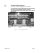
Figure 7 Terminal Board Layout
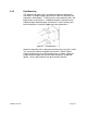
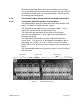
There is a green wire with a yellow stripe attached to a threaded post
on the base plate. The free end of this wire is stripped and must be
installed in the terminal J4-1. J4-1 is the left-most terminal of the
largest terminal plug (the plug on the lower-right of figure 7) and is
marked “S” on a yellow background. This is a redundant electrical
connection to the Protective Earth for the terminals marked “SHD”
which are to be used for connecting cable shields, drain wires, and
grounding tag wires from metal cable glands as specified elsewhere in
this manual.
Section #1
Section #2
Section #3