
User guide


20832-01 Rev 05
Page 6-1
6 TRANSMITTER INSTALLATION
Table of Contents
6 TRANSMITTER INSTALLATION ..................................................................................... 6-1
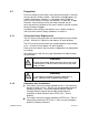
6.1 Preparation .............................................................................................................. 6-3
6.1.1 Transmitter Power Requirements ..................................................................... 6-3
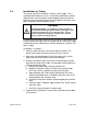
6.1.2 Hazardous Area Installations ........................................................................... 6-3
6.1.2.1 European Zone 2 Rated Equipment ............................................................. 6-5
6.1.3 Transmitter Environmental Conditions ............................................................. 6-5
6.2 Transmitter Mounting Instructions ............................................................................ 6-6
6.2.1 Bulkhead Mounting .......................................................................................... 6-6
6.2.2 Pipe Mounting .................................................................................................. 6-7
6.3 Transmitter Cable Connections ............................................................................... 6-8
6.3.1 Transmitters With Non-Pluggable Terminal Blocks .......................................... 6-8
6.3.2 Transmitters With Pluggable Terminal Blocks .................................................. 6-9
6.3.3 Transmitter Housing Cable Entry ................................................................... 6-10
6.3.4 Transmitter Output, Sensor and Sensor Head Connections ........................... 6-11
6.3.4.1 Transmitters With Non-Pluggable Terminal Blocks ..................................... 6-11
6.3.4.2 Transmitters With Pluggable Terminal Blocks ............................................ 6-12
6.3.4.3 Transmitter Output Connections (Section #1) ............................................. 6-13
6.3.4.3.1 Transmitters With Non-Pluggable Terminal Blocks ............................... 6-14
6.3.4.3.2 Transmitters With Pluggable Terminal Blocks ...................................... 6-15
6.3.4.4 Transmitter Input Connections (Section #2) ............................................... 6-16
6.3.4.4.1 Transmitters With Non-Pluggable Terminal Blocks ............................... 6-16
6.3.4.4.2 Transmitters With Pluggable Terminal Blocks ...................................... 6-16
6.3.4.5 Sensor Head to Transmitter Cable Connections (Section #3) .................... 6-17
6.3.4.5.1 Non-armored cable installation ............................................................. 6-18
6.3.4.5.2 Armored cable installation .................................................................. 6-202
6.3.5 Transmitter Electrical Power Cable Installation .............................................. 6-24
6.3.5.1 AC-Powered Passive Sonar Meter ........................................................... 6-255
6.3.5.2 DC-Powered Passive Sonar Meter ........................................................... 6-266
6.3.6 Sensor Calibration Label .............................................................................. 6-277
List of Figures
Figure 1 Bulkhead Mount Hole Pattern .............................................................................. 6-6
Figure 2 Pole Mount Kit ..................................................................................................... 6-7
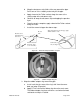
Figure 3 Power and Signal Interconnects .......................................................................... 6-8
Figure 4 Power and Signal Interconnects .......................................................................... 6-9
Figure 5 Transmitter Housing Cable Gland Holes ............................................................ 6-10
Figure 6 Terminal Board Layout ....................................................................................... 6-11
Figure 7 Terminal Board Layout ....................................................................................... 6-12
Figure 8 Transmitter Output Terminals ............................................................................ 6-14
Figure 9 Transmitter Output Terminals ............................................................................ 6-15
Figure 10 Transmitter Sensor Terminals ............................................................................ 6-16
Figure 11 Transmitter Sensor Terminals ............................................................................ 6-16
Figure 12 Transmitters With Non-Pluggable Terminal Blocks ............................................ 6-19
Figure 13 Transmitters With Pluggable Terminal Blocks .................................................... 6-19