
User guide

20833-01 Rev 04
Page 7-16
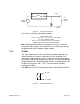
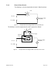
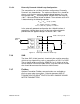
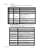
7.6.1.2.2 Status Line
The code for information in the status line shown in Figure 52 is
defined as follows:
ID
Characters
Description
Values
S
20
Status Messages
See Status Messages Table below
Q
11
Quality Field
See Quality Field Message Table below
M
4
Mode
See Operating Mode Message Table below
E
1
Ethernet
Communication
E – Ethernet activity present
C
1
Other
Communications
H - Hart Message received
M - MODBUS communications
M (reverse) – MODBUS in write mode
F – Fieldbus
F (reverse) – Fieldbus in write mode
S - Serial Activity
Blank - No Activity
W
1
Write Protect
W – Write Protected or
[blank] – Not Write Protected
E
1
Event Log Updated
! – Event Log Updated or [blank] – No change to
Event Log since last check
A
1
Activity
|/-\ (Cycle changes indicate activity)
Table 3 Status Line Code
Status Messages - ‘S’:
A number of status messages can be displayed in the 20 character
status message field. They are as follows:
Status Message
Description
INITIALIZE MODE
DSP is acquiring data to calculate a measurement
VF INITIALIZE MODE
DSP is acquiring data to calculate a flow measurement
BELOW MIN VF QUALITY
Quality of measured sensor data is below a configured
minimum for a Vortical Flow measurement
GVF INITIALIZE MODE
DSP is acquiring data to calculate a GVF
measurement
INVALID SOS DATA
DSP is acquiring data to calculate a SOS
measurement
BELOW MIN SS QUALITY
Quality of measured sensor data is below a configured
minimum for a GVF measurement
BELOW MIN QUALITY
Quality of measured sensor data is below a configured
minimum for VF and SOS measurement
SENSOR OVERLOAD
DSP indicates sensors are overloaded
DSP FAILURE - n
A DSP communication error occurred
Table 4 Status Line Messages