Table of Contents P/N 20823-01 Rev-13 Installation Manual P/N 20822-01 Rev.
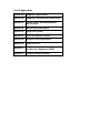
List Of Appendices Appendix A SONARtrac Specifications Appendix B SONARtrac EC Declaration of Conformity Appendix C System Control Drawing SONARtrac, Non-Incendive Appendix D Material Safety Data Sheets Appendix E Conversion Factors Appendix F Physical Properties of Water Appendix G End User License Agreement Appendix H Spare Parts List Appendix I Directive 2002/96/EC On Waste Electrical and Electronic Equipment (WEEE) Appendix J Troubleshooting Procedures
1 INTRODUCTION with INSTALLATION CHECKLIST Table of Contents 1 INTRODUCTION with INSTALLATION CHECKLIST ....................................................... 1-1 1.1 Introduction .............................................................................................................. 1-1 1.2 Sensor Head Description and Function .................................................................... 1-2 1.3 Transmitter Description and Function...........................................................
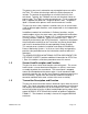
The process pressure is reduced to near-atmospheric pressure within the TAM. This allows dissolved gas within the fluid to come out of solution. The amount of entrained gas or air within the fluid is then calculated. Typically, the TAM bolts on to an existing plant I-beam or process pipe. The TAM is usually connected to an ~1-inch sample tap and is supplied with about 20 – 30 gpm of process flow. The process liquid is returned to the process once the measurement is made.
1.4 Intellectual Property Notices Passive Sonar Process Monitoring Products may be covered by one or more of the following granted U.S. Patent(s): 6,354,147; 6,435,030; 6,587,798; 6,601,458; 6,609,069; 6,691,584; 6,732,575; 6,813,962; 6,862,920; 6,889,562; 6,988,411; 7,032,432; 7,058,549; 7,062,976; 7,086,278; 7,110,893; 7,121,152; 7,127,360; 7,134,320; 7,139,667; 7,146,864; 7,150,202; 7,152,003; 7,152,460 Other patents are pending; see www.cidra.com for the latest listing of patents.
1.7 Passive Sonar EC Declaration of Conformity The EC Declaration of Conformity provides the justification for the CE marking of a product. It identifies all of the EC Directives that apply to the product along with the Standards that the product was designed to or tested against to demonstrate compliance with those directives. CE marking is a requirement only for products sold in the European community. The EC Declarations of Conformity are shipped with the SONAR process monitoring system.
1.8 Installation Checklist The purpose of this section is to provide a checklist for installing the passive sonar process monitoring system. 1. ___Determine installation location electrical classification rating. 2. ___Ensure equipment to be installed has the correct electrical classification. 3. ___Read Installation Manual. 4. ___Clean pipe per Manual Section 5.5. 5. ___Measure pipe using PI Tape and ultrasonic thickness gauge.
*** This Page is Blank*** 20825-01 Rev 07 Page 1-6
2 EQUIPMENT SAFETY COMPLIANCE Table of Contents 2 EQUIPMENT SAFETY COMPLIANCE ............................................................................ 2-1 2.1 Safety ...................................................................................................................... 2-1 2.2 North American Emissions....................................................................................... 2-1 2.3 European Emissions and Immunity.............................................................
Laboratory Use - EMC requirements as well as EN 55011 Industrial, Scientific, and Medical (ISM) Radio Frequency Equipment - Radio Disturbance Characteristics - Limits and Methods of Measurement. For the purpose of Electromagnetic Compatibility (EMC) requirements, this product is categorized as Group 1, Class A ISM equipment.
3 GENERAL SAFETY GUIDELINES Table of Contents 3 GENERAL SAFETY GUIDELINES .................................................................................. 3-1 3.1 Introduction.............................................................................................................. 3-1 3.2 Safety Precautions .................................................................................................. 3-2 3.3 Definitions of Symbols ................................................................
3.2 Safety Precautions The following style of Warnings and Cautions are used throughout the manual to draw attention to information regarding personnel safety and equipment care. They are intended to supplement but not replace local or plant safety procedures. WARNING Situation has the potential to cause bodily harm or death. CAUTION Situation has the potential to cause damage to property or equipment. 3.
3.3.3 General Warnings and Cautions Observe these rules when operating or servicing this equipment: Prior to operation of this equipment, personnel should read the instruction manual thoroughly. Trained personnel must carry out service on this equipment. Follow all warnings on the unit and in the operating instructions. This product should only be powered as described in the manual. Read the instructions for proper input voltage range selection.
3.3.4 Additional Warnings for installations in Hazardous Areas such as Class I, Division 2 In addition to the General Warnings and Cautions, observe these rules when operating or servicing this equipment to mitigate the risks associated with explosive gas atmospheres. (For ATEX Zone 2 installations, additional warnings may be found in the SONAR PROCESS MONITORING SYSTEM SUPPLEMENT FOR ATEX ZONE2 SAFETY.) Only equipment marked with the appropriate hazardous area rating should be installed in those areas.
Fuse replacement must be performed by trained service personnel. Disconnect power to transmitter prior to replacing fuse(s). Use only the specified fuse(s) with the correct type number, voltage and current ratings as referenced in the appropriate locations in the service instructions or on the equipment. WARNING EXPLOSION HAZARD - DO NOT REMOVE OR REPLACE FUSES UNLESS POWER HAS BEEN DISCONNECTED OR THE AREA IS KNOWN TO BE FREE OF IGNITABLE CONCENTRATIONS OF FLAMMABLE GASES OR VAPORS.
***This Page is Blank*** 20829-01 Rev 03 Page 3-6
4 UNPACKING AND PARTS LIST Table of Contents 4 4.1 4.2 4.3 4.4 UNPACKING AND PARTS LIST ................................................................................. 4-1 Unpacking ............................................................................................................... 4-1 Inventory of Parts .................................................................................................... 4-2 Class I, Division 2 Label ...........................................................
4.2 Inventory of Parts Table 1 lists the parts contained in the shipping containers. Description Passive Sonar Monitoring System Sensor Head Cable Installation Hardware Sealant, Joint and Thread, PTFE Paste, 3.
5 SENSOR INSTALLATION Table of Contents 5 SENSOR INSTALLATION ............................................................................................... 5-1 Table of Contents ................................................................................................................ 5-1 List of Figures ..................................................................................................................... 5-1 List of Tables............................................................
Figure 11 Figure 12 Figure 13 Figure 14 Figure 15 Figure 16 Figure 17 Figure 18 Figure 19 Figure 20 Figure 21 Figure 22 Figure 23 Figure 24 Figure 25 Figure 26 Figure 27 Figure 28 Figure 29 Figure 30 Figure 31 Figure 32 Figure 33 Figure 34 Figure 35 Figure 36 Figure 37 Figure 38 Figure 39 Figure 40 Figure 41 Figure 42 Figure 43 Figure 44 Figure 45 Figure 46 Figure 47 Figure 48 Figure 49 Figure 50 Figure 51 Sensor Band Spacer Gauge ............................................................................
5.1 Class I, Division 2, Groups A, B, C, and D Rated Equipment As a rule, installation or removal of Sensor Heads in Hazardous areas should not be performed without a hot work permit indicating that the areas where the sensor band is to be handled are free of explosive gasses. Check to make sure that the ambient and process temperatures of the installation location are consistent with the temperature ratings of the Sensor Head (see Appendix A).
5.3 Installation Tools The Basic Installation Tool Kit contains all tools required for typical installations. Additional tools may be required based on particular installation needs.
The following expanded tool kit contains additional high precision pipe measurement tools and additional hand tools.
Both tool kits are available from Customer Support. Please contact them for additional information. WARNING EXPLOSION HAZARD - Use of power tools for installation may or may not be acceptable for use in hazardous areas. Review the terms of the hot work permit prior to use. 5.4 Sensor Installation Guidelines The following are general installation guidelines and recommendations for installing a passive sonar meter sensor.
5.5 Process Piping Considerations The passive sonar meter sensor head assembly mounts on the process pipe. There is no need for breaking any process connections or for shutting down the process. The sensor head must be installed in a location that ensures a full pipe during operation. Check the sensor head label to ensure the sensor head is approved for the area hazard rating in the location where it will be installed. 5.5.1 Pipe Preparation Remove pipe insulation if it is present.
5.5.2 Determine the Pipe Inner Diameter (ID) Record the nominal pipe size based on the pipe size and pipe schedule, as this will be input into the transmitter. Alternatively, measure and calculate the pipe ID. Accurately measure the pipe outside diameter (OD). Use an ultrasonic thickness measurement gauge to determine the wall thickness (tw) at a minimum of 4 locations equally spaced around the pipe and average the measurements. Calculate the pipe inner diameter (ID = OD – (2tw)).
Sensor band shorting plug Alignment pins (typical 2 places) Sensor attachment screw assembly (typical 9 places) Flow direction arrow Attachment rails Figure 1 Sensor Band Screw and Alignment Pins Wrap the sensor band around the pipe and slide the alignment pins on the attachment rail through their mating holes on the opposite attachment rail. If the process pipe has a welded seam, align the gap between the sensor attachment rails along the pipe weld seam.
Start with the center most screw and tighten screws, alternating from side to side, 3 - 4 turns at a time. Refer to Figure 2 for the screw tightening sequence. Note: Repeat the tightening sequence only until the Belleville disc springs on the screws begin to compress. The sensor screw stack up assembly is illustrated in Figure 3.
Further tightening of the sensor band screws is made while using the sensor band spacer tool (shown below) furnished with the sensor band. The spacer tool is used to set the compression on the Belleville washers referred to above. Refer to Table 3 for the appropriate spacer tool based on sensor band part number.
Final sensor band screw tightening is as follows: A. For sensor bands sized for 6” and smaller pipe: 1. Tighten screws #1 - 7 an additional one-half turn in the numbered sequence given in Figure 2. Do not tighten screw #8 & 9 (screws on either end of the sensor band). B. For sensor bands sized for 8” and larger pipe: 1. Starting at screw #1 in Figure 2, tighten each screw an additional one-half turn in the given numbered sequence. 2.
5.6.2 HD Product / Segmented Sensor Band Installations Wrap the compliant sheet (optional) around the process pipe. The ends of the compliant sheet should be positioned at the weld seam on the pipe (if there is one). Refer to the following figures.
Position the passive sonar meter sensor band assembly on the pipe with the polyimide film (amber colored) against the compliant layer. Important: The attachment rails on an HD / segmented sensor band must be installed on the top of a horizontal flowing pipe. Slide the alignment pins on the attachment rail through their mating holes on the opposite attachment rail. If possible, orient the flow direction arrow on the sensor assembly with the direction of flow within the pipe.
Sensor Band P/N Spacer Gauge Socket Head Screw P/N Hex Size (inch) Band Attachment Rail Size (Ref) 20669- ALL SIZES 20143-01 7/64 1/8 x 3/8 20690- ALL SIZES 20143-04 5/32 1/4 x 1/2 Table 5 Gauge Block and Screw Size Start with the center most screw and tighten screws, alternating from side to side, 3 - 4 turns at a time. Refer to the following figure for the screw tightening sequence. Note: Repeat the tightening sequence only until the Belleville disc springs on the screws begin to compress.
Sensor screw Sensor Belleville washers convex side Sensor Belleville washers concave side Sensor screw spacer (may be integral to screw head) Note: 10 Belleville Washers on 2-16” bands Belleville washers and spacer compressed against screw head )()()()()()()( Figure 10 Note: Sensor bands 18” and larger have 14 Belleville washers per screw arranged as shown Sensor Band Screw Assembly Further tightening of the sensor band screws is made while using the sensor band spacer gauge (shown below) furnishe
Side view Sensor screw with Belleville washers compressed (typ) Sensor screw spacing tool installed on sensor screw Figure 12 Sensor Band Spacing Tool Installed on Sensor Screw Note: Ensure the spacer tool is perpendicular to the attachment rail to ensure proper tightness. Remove the tool, move to the next sensor screw, and repeat the tightening on each of the sensor screws. Important: Tighten each screw once only. Do not retighten each screw using the gauge.
Sensor cable installed in cable retaining clip Sensor screws tightened Sensor cable connector with shorting plug installed Alignment pins Compliant sheet Figure 13 Installed Sensor Band CAUTION Over-tightening of fasteners may damage threads on the sensor. Under tightening may affect flow meter performance. Always use the sensor fastener spacer tool to ensure proper fit of the sensor assembly. 5.6.
5.6.4 Sensor Band Thermal Barrier Installation Install the sensor band thermal barrier if one was included with the System. Refer to the figure below. 1. Align the slit on the thermal barrier with the sensor band to preamplifier cable. 2. Wrap the thermal barrier over the sensor attachment rails. 3. Continue to wrap the thermal barrier around the sensor band. 4. Seal at the Velcro strips and install the straps through the D-rings on the thermal barrier. 5.
5.7 Sensor Cover Installation The upper sensor cover assembly outside and inside is illustrated in the following figures. Covers are made of fiberglass or stainless steel. Figures 15 and 16, below, show the fiberglass cover style, but the layout of all styles is essentially the same. The differences in installation will be called out in the following sections.
It is helpful to have a second person available to help when installing the cover assembly. When the sensor head is installed on a horizontal pipe, the sensor cover should be installed such that the transmitter cable connector socket is located within the 105° arcs shown in the following figure. Do not install the cover with the transmitter cable connector socket installed downward. (An electrical pre-amplifier board is mounted on the inside of the cover.
5.7.1 Fiberglass Cover Model SH-XXX-XX-XA-XXX-XX Installation The installation procedures for Fiberglass Cover Model Number SHxxx-xx-xA-xxx-xx (where “x” is any alphanumeric character) is found on the following pages. These covers are readily recognized by their having latches and strikes to secure the cover halves together. Note: These are the only model number covers currently available with ATEX Zone 2 certification.
The passive sonar sensor head cover is illustrated in the following figure. Breather vent Access cover Connector Handle Boot seal Edge seal TPE rubber Latch and keeper Figure 19 Fiberglass Cover WARNING The handles on the cover are designed for holding the cover in place during installation. The handles are not designed or rated for hoisting the cover. Use a proper lifting sling to properly secure cover to lifting rope when hoisting cover. Each pipe size has a cover designed to fit that size pipe.
5.7.1.1 Cover Installation Procedure Care must be taken during installation of the sensor band cover to ensure the sensor band cable does not become pinched between the cover halves. The problem may show up as a sensor failure during sensor tests and operation of the meter. This potential problem is most likely to occur in small size meters (<6-inch) due to the length and stiffness of the sensor band cable. 5.7.1.
5.7.1.3 Vertical Pipe Installation Important: A Sensor Cover Support Installation Kit is recommended when installing the cover assembly on vertical pipes. Contact Customer Support if you do not have a Sensor Cover Support Installation Kit. 1” wide lower ratcheting strap Supports Cover upper support strap (hook and loop) Figure 21 Sensor Cover Support Installation Kit Installation of the sensor cover on vertical pipes is as follows: 1. Install the sensor band. 2.
c. Thread the strap loose end through the take-up spindle and pull slack strap through the spindle before tightening using the ratchet. Cover upper support strap Cover lower support strap assembly Lower cover boot seal sitting on cover lower support strap assembly Figure 22 Sensor Cover Support Installation Kit on Pipe 8. Lift the upper sensor cover into place on the cover lower support strap assembly. 9. Install a cover support strap between the cover upper handle and the cover upper support strap.
Cover top support strap Cover lower support strap Figure 23 Sensor Cover Installed on Sensor Support Installation Kit 12. Ensure the cover halves are aligned and then buckle the cover latches. 13. Remove the cover support strap (upper) assembly. 14. .DO NOT REMOVE THE COVER LOWER SUPPORT STRAP. THE COVER WILL SLIP AND DAMAGE THE SENSOR BAND. 15. Install sensor band upper boot seal clamps per Section 5.7.1.2. 16. Install sensor band lower boot seal clamps per Section 5.7.1.2.
5.7.1.4 Boot Seal Clamp and Band Installation The boot seal clamp or band is used to seal the cover boot seal to the process pipe. Cover sizes 2-inch through 8-inch use a stainless steel T-bolt saddle clamp. Cover sizes 10-inch and larger use a stainless steel band and buckle fastener. These are illustrated in the following figures. NOTE: Always install the upper boot seal clamp first on vertical pipe installations. Figure 24 Tee-Bolt Saddle Clamp Pre-installed buckle Figure 25 5.7.1.4.
5.7.1.4.2 Boot Seal Band Installation The boot seal band used on cover sizes 10-inch and larger will be shipped cut to length for the cover size with the retaining buckle preinstalled. The boot seal band should be completely installed on one end of the cover and then repeated on the other end. Pre-installed buckle Figure 27 Boot Seal Band Position the buckle on the band of the cover so it is in line with the lifting handles of the upper cover in the groove on the boot seal.
Figure 29 ® BAND-IT Model C00169 Tool Use Verify the band is still aligned within the grooves on the boot gasket and over the first wrap of the band, and the band buckle is positioned in line with the cover handle. Tension the band until the resistance on the tool handle is constant (i.e. the band does not slide easily through the buckle). The boot seal should be tight against the process pipe. Verify the band is in the boot seal groove. Tighten the band set screw to lock the band in place.
Repeat the band installation procedure for the opposite end of the cover.
5.7.2 Stainless Steel Cover Model SH-XXX-XX-02(or 05 or 32)XXX-XX Installation This section covers installation of Stainless Steel Covers Model Numbers SH-xxx-xx-02-xxx-xx or SH-xxx-xx-05-xxx-xx or SH-xxx-xx32-xxx-xx, where “x” is any alphanumeric character. The stainless steel cover is illustrated in the following figure.
Figure 34 ® BAND-IT Model C00169 Banding Tool CAUTION ® Use of a BAND-IT Model C00169 Banding Tool (or equivalent) is necessary for properly installing sensor cover. Failure to use this tool may void system warranty. Remove the sensor cable access panel on the cover and place the upper cover assembly on the pipe. Note: Ensure the sensor cable connector is accessible through the sensor cable access panel. (If necessary reposition cover or cable connector.
5.7.2.1 Boot Gasket Band Installation The boot gasket band will be shipped cut to length for the cover size with the retaining buckle pre-installed. The boot gasket band should be completely installed on one end of the cover and then repeated on the other end. Pre-installed buckle Figure 36 Boot Gasket Band Kit Position the buckle on the band over the gasket protector plate located on the top of the upper cover outboard of the handles.
loose enough so the band will still slide through the buckle. Repeat on the opposite end of the cover. Splice protector plate centered on gasket splice Lift band with needle nose pliers or screw driver Figure 38 Splice Protector Plate Installation Install the BAND-IT® Model C00169 tensioning tool by inserting the band through the cutter bar and slide lock. Note: This tool is asymmetric. The tool will pull in opposite directions when installed on opposite ends of the cover.
Tighten the set screw to lock the band in place. The band will be dimpled by the set screw. Allen wrench tightening set screw on buckle Buckle over protector plate Boot gasket tight against pipe Figure 40 Final Alignment and Securing of Gasket Band Once the set screw has been fully tightened, loosen the tensioning tool and bend the tool and band up and over the buckle. It is not necessary to cut excess band material (allows for re-tightening or reuse of band if necessary).
5.7.3 Fiberglass Cover Model SH-XXX-XX-01(or 06)-XXX-XX Installation This section covers installation of Fiberglass Covers with Model Numbers SH-xxx-xx-01-xxx-xx or SH-xxx-xx-06-xxx-xx, where “x” is any alphanumeric character. These covers are readily identified by their having nut and bolt fasteners along their flange. Remove the sensor cable access panel from the sensor upper cover assembly.
Refer to the following figure. Align the center alignment holes on the sensor cover. Install a 3” long 3/8” diameter alignment bolt, with washer under the bolt head, in center holes on both sides of the cover. Install a washer and nut on the alignment bolts. Install a 5/16”-18 x 1.5” tin plated 316 SST bolt with washer into each of the 12 cover bolt holes in the upper cover.
Alignment bolts 11 7 3 1 5 9 10 6 2 4 8 12 Figure 44 Sensor Cover Bolt Tightening Sequence Note: The gaskets on the cover assembly will compress and conform to the pipe surface during installation. Upon removal the gasket will relax a little and will still provide proper sealing if re-installed at the same location from where it was removed.
5.7.4 Sensor Assembly Cable Connection Remove the tape (if it was used) that was temporarily installed to retain the sensor connector under the cover access panel. Remove the factory installed shorting plug (if so equipped) from the sensor cable connector. Save this shorting plug as it will be used if sensor removal from the pipe is necessary. [Note: Sensor bands with model numbers ending in “-R” do not require shorting plugs and are delivered without them.
5.7.5 Rain Boot Installation A sensor cover rain boot will be installed on the upward facing end of sensor covers when the sensor head is installed in vertical applications. The rain boot serves as a secondary seal against water leakage under the cover (the sensor cover seal is primary seal). Note: The stainless steel and fiberglass covers with latches do not need a rain boot. Wrap the elastomer rain boot around the sensor cover and pipe.
5.7.6 Sensor Calibration Label The sensor band is shipped with two labels enclosed with it. The label lists the sensor part number, serial number, date of manufacture and three calibration factors. This information will be entered into the transmitter during setup. Affix one of the labels to the outside of the access panel of the sensor cover as shown below. The second label should be installed on the inside of the transmitter cover.
5.8 Sensor to Transmitter Cable Connections The sensor to transmitter cable is used to transmit sensor signals and information between the transmitter and the sensor, and provides electrical power to the sensor pre-amplifier board mounted in the sensor cover. The sensor to transmitter cable consists of 12 twisted pairs of 20 AWG conductors with an overall cable shield encased in a PVC jacket. The standard cable has an operating range of -4 ºF to 221 ºF (–20 ºC to 105 ºC).
5.9 Installations on Tubing The sensor head will fit on process tubing as well as pipe. This is accomplished through the use of a sensor band specifically sized for tubing and the use of elastomer strips wrapped around the tube (in order to increase the tube diameter to that of pipe) in the areas of the pipe seal gaskets on the fiberglass cover. WARNING EXPLOSION HAZARD – The ATEX Zone 2 approval applies to Sensor Heads with integral gaskets sized to fit the pipe.
Process tube Clean areas for elastomer strips and sensor Distance between elastomer strips (cover end seals) Figure 48 20831-01 Rev 05 Wrap elastomer strip around pipe; apply Teflon sealant to ends Seams (may or may not align Elastomer Strip Installation on Tubes Page 5-45
5.10 Special Installation Instructions for Covers with Spacers The passive sonar meter is able to be installed on non-standard size pipes found at some installation sites. WARNING EXPLOSION HAZARD – The ATEX Zone 2 approval applies to Sensor Heads with integral gaskets sized to fit the pipe. Zone 2 certification prohibits the use of spacers of any kind. Contact Customer Support about whether an ATEX Zone 2 solution exists for a particular pipe diameter.
b. Wrap the elastomer strip 3/4ths of the way around the pipe. Pull it taut so it lies smoothly and evenly on the pipe. c. Apply a bead of the Teflon sealant along the seam at the starting edge of the elastomer strip. d. Continue to wrap the elastomer strip overlapping the previous layer. e. Once the wrap is complete, apply a bead of the Teflon sealant along the seam. f. Install the second strip per the above steps.
*** This Page is Blank*** 20831-01 Rev 05 Page 5-48
6 TRANSMITTER INSTALLATION Table of Contents 6 TRANSMITTER INSTALLATION..................................................................................... 6-1 6.1 Preparation .............................................................................................................. 6-3 6.1.1 Transmitter Power Requirements ..................................................................... 6-3 6.1.2 Hazardous Area Installations .......................................................................
Figure 14 Figure 15 Figure 16 Figure 17 Figure 18 Figure 19 Figure 20 Figure 21 Figure 22 NEMA 4X Rated Connector ............................................................................... 6-20 IP-65 Rated Connector ...................................................................................... 6-21 Armored Cable Stiffener Plate Installation.......................................................... 6-22 Removal of Cable Armor......................................................................
6.1 Preparation Prior to installing the transmitter, verify that the transmitter is rated for the area where it will be installed. Consider the available power, the ambient temperature, whether it is a Hazardous Area (Explosive gasses) or an Ordinary Location, and whether it is to be wall- or pipemounted. If the markings on the transmitter received are not consistent with the conditions of the area in which it must be installed, contact Customer Support.
For installation in Hazardous areas, both the Sensor Head and the Transmitter have to have the same hazardous area approvals even if only one of the two pieces is to be installed in a hazardous area. WARNING EXPLOSION HAZARD - Installation of equipment in hazardous areas must comply with the appropriate control drawing for the particular model numbers.
Avertissement Risque d’explosion – La substitution de composants peut rendre ce matériel inacceptable pour les emplacements de Classe i, Division 2 Warning Explosion hazard - Do not disconnect from mains power while circuit is live unless the area is known to be free of ignitable concentrations of flammable gases or vapors. Avertissement Risque d’explosion – Avant de déconnecter l’équipement, couper le courant ou s’assurer que l’emplacement est désigné non dangereux. 6.1.2.
6.2 Transmitter Mounting Instructions The transmitter is furnished with a Bulkhead (wall or panel surface mount) Installation Kit. An optional Pipe Installation Kit is also available. The maximum sensor head to transmitter cable length is 300 feet. Select an installation location that allows for easy and safe access to the transmitter. Ensure the local ambient temperature range is within the operating temperature limits of the transmitter.
6.2.2 Pipe Mounting The optional Pipe Mount Kit is designed to allow for mounting the transmitter assembly to pipes up to 10-inch (250 mm) diameter and equivalent sized I-beams. The kit consists of two mounting rails, two band clamps, and fasteners. (Additional lengths of clamps can be added for larger diameter pipes and I-beams. Please contact your local distributor or Customer Support for more information.
6.3 Transmitter Cable Connections 6.3.1 Transmitters With Non-Pluggable Terminal Blocks The following figure illustrates the basic power and signal connections for transmitters with non-pluggable (fixed) terminal blocks. The recommended torque for the terminal screws is 4.4 to 5.3 lb f-inch (0.5 to 0.6 Nm).
6.3.2 Transmitters With Pluggable Terminal Blocks The following figure illustrates the basic power and signal connections for transmitters with pluggable terminal blocks. The recommended torque for the terminal screws is 4.4 to 5.3 lb f-inch (0.5 to 0.6 Nm). The recommended torque for the screws that secure the terminal blocks to the base is 3.5 to 4.4 lbf-inch (0.4 to 0.5 Nm).
6.3.3 Transmitter Housing Cable Entry Power, sensor signal, and input /output signal cables enter the transmitter housing through cable glands. The cable glands also provide strain relief for the cables. Always ensure they are fully tightened. The following figure illustrates where each of the cable glands are installed.
Whenever metal cable glands are used in hazardous areas, always use the grounding tags and connect the wire from those tags to one of the terminals marked “SHD” on the terminal blocks. This will ground the exposed metal cable gland. 6.3.4 Transmitter Output, Sensor and Sensor Head Connections 6.3.4.1 Transmitters With Non-Pluggable Terminal Blocks The following figure shows the layout of the transmitter terminal strip board. This board is divided into three sections.
6.3.4.2 Transmitters With Pluggable Terminal Blocks The following figure shows the layout of the transmitter terminal strip board. This board is divided into three sections. The Section#1 terminal blocks are for transmitter outputs. These signals are not certified Non-incendive field wiring. The Section #2 terminal blocks are for external sensor inputs (pressure and temperature). For Class I, Zone 2, ATEX rated Transmitter Model TB8-xx-xx-xx-03 these are to be treated as nonincendive field wiring.
6.3.4.3 Transmitter Output Connections (Section #1) User supplied data output cable size AWG 22 to AWG 16 (0.326 mm2 to 1.31 mm2) is installed through a cable gland in the furthest left hole on the transmitter housing and attached to the appropriate terminal block connection points. The hole is sized for a 3/4 inch NPT or M25 cable gland fitting (1-1/16 inch (25.4 mm) hole).
6.3.4.3.1 Transmitters With Non-Pluggable Terminal Blocks The following figure provides a close-up of the transmitter output terminals (Section #1 of the terminal board) with their functions listed in the following table. These outputs can be connected as appropriate to permit communications between the transmitter and other equipment. The recommended torque for the terminal screws is 4.4 to 5.3 lb f-inch (0.5 to 0.6 Nm).
6.3.4.3.2 Transmitters With Pluggable Terminal Blocks The following figure provides a close-up of the transmitter output terminals (Section #1 of the terminal board) with their functions listed in the following table. These outputs can be connected as appropriate to permit communications between the transmitter and other equipment. The recommended torque for the terminal screws is 4.4 to 5.3 lb f-inch (0.5 to 0.6 Nm). The recommended torque for the screws that secure the terminal blocks to the base is 3.
6.3.4.4 Transmitter Input Connections (Section #2) In some cases, a pressure or temperature transducer signal is used as an input to the transmitter (currently not used for VF-100 system). These terminals are shown in the following figures. The transducers must be 2-wire loop-powered 4-20mA current transmitters. The 2 wires must be “floating” (i.e. not groundreferenced) for safety reasons and because they are powered from +/12V from the Transmitter. 6.3.4.4.
The recommended torque for the screws that secure the terminal blocks to the base is 3.5 to 4.4 lbf-inch (0.4 to 0.5 Nm). For Class I, Zone 2, ATEX rated Transmitter Model TB8-xx-xx-xx-03 these are to be treated as non-incendive field wiring. 6.3.4.5 Sensor Head to Transmitter Cable Connections (Section #3) The sensor head to transmitter cable is used to transmit sensor data and information between the transmitter and the sensor head, and provides power to the electronics mounted in the sensor cover.
WARNING For ATEX Class I, Zone 2 applications, the SENSOR HEAD TO TRANSMITTER CABLE must be installed in accordance with EN60079-14 for Non-incendive circuits. Whether armored or unarmored cable, the cable gland must be ATEX certified and IP55. See SONAR PROCESS MONITORING SYSTEM SUPPLEMENT FOR ATEX ZONE 2 SAFETY for additional info and requirements 6.3.4.5.1 Non-armored cable installation Remove 10 - 12 inches (25 – 30 cm) of outer jacket from the transmitter end of the cable.
Figure 12 Figure 13 20832-01 Rev 05 Transmitters With Non-Pluggable Terminal Blocks Transmitters With Pluggable Terminal Blocks Page 6-19
The following table lists the cable connector pin-out for cables equipped with the NEMA 4X rated connector (Figure 14).
The following table lists the cable connector pin-out for cables equipped with the IP-65 rated connector (Figure 15).
6.3.4.5.2 Armored cable installation For those installations that will use armored cable between the sensor head and transmitter, install the P/N 20448-01 transmitter housing stiffener plate (shipped with the armored cable) in the transmitter housing. Ensure the plate is installed with the bent edge up and located toward the front of the transmitter housing. The stiffener plate is held in place by the cable gland fittings.
to the connector body and then final tighten 1-1/2 rotations using 15/8” wrenches. Hand-tighten and then final tighten the compression nut to the connector body 1 rotation using 1-5/8” wrenches. Cut and remove the conductor outer sheath about 3/4" (19mm) from the end of the entry component. Remove foil outer wrap and foil from each pair of conductors. As each pair is unwrapped, twist each pair of conductors to keep them together as pairs.
6.3.5 Transmitter Electrical Power Cable Installation The right-most hole in the bottom of the transmitter box is used to bring electrical power into the transmitter box. The hole is sized for a 3/4 inch NPT (M25) fitting (1-1/16-inch / 25.5 mm diameter). The system installation should include a marked and appropriatelyrated switch or circuit breaker within close proximity of the Transmitter and within easy reach of the operator.
6.3.5.1 AC-Powered Passive Sonar Meter The AC version of the passive sonar meter will accept 100 – 240 VAC, 50/60 Hz power. Power cables of size AWG 18 minimum to AWG 12 maximum (1.04 mm2 to 3.31 mm2), with a ground conductor, are required. WARNING Always use a non-current-carrying safety ground. Failure to use a non-current-carrying safety ground could result in injury or death.
6.3.5.2 DC-Powered Passive Sonar Meter Any voltage within the range of 18 – 36 VDC can be applied to the DC version of the passive sonar meter. Power cables of size AWG 18 minimum to AWG 12 maximum (1.04 mm2 to 3.31 mm2), with a ground conductor, are required.
6.3.6 Sensor Calibration Label The sensor band is shipped with two labels attached to it. The label lists the sensor band part number, serial number, date of manufacture and three calibration factors. This information will be entered into the transmitter during setup. If not done previously, install the Sensor Band Assembly label on the inside of the transmitter cover (the other label goes on the sensor head access panel).
*** This Page is Blank*** 20832-01 Rev 05 Page 6-28
7 TRANSMITTER FUNCTIONS Table of Contents 7 TRANSMITTER FUNCTIONS ......................................................................................... 7-1 7.1 Introduction.............................................................................................................. 7-3 7.2 Transmitter Layout ................................................................................................... 7-3 7.2.1 Transmitters With Non-Pluggable Terminal Blocks .....................................
Figure 16 Figure 17 Figure 18 Figure 19 Figure 20 Initialization Mode .......................................................................................... 7-19 VF/GVF Screen ............................................................................................. 7-19 Typical Menu Screen ..................................................................................... 7-23 Editing Parameter By Digits ...........................................................................
7.1 Introduction The following section of this manual will present the transmitter layout and menus in the passive sonar meter. The SONAR PROCESS MONITORING SYSTEM SUPPLEMENT FOR ATEX ZONE 2 SAFETY provides additional information for ATEX Class I, Zone 2 installations. 7.2 Transmitter Layout The following pages illustrate the passive sonar meter transmitters.
7.2.
7.2.
7.3 Transmitter Output Definitions The following figures show a diagram of the output portion of the terminal board. The outputs of the transmitter are connected to provide communication between the transmitter and other equipment.
7.3.1 COMM This denotes the connection point for serial digital communications. Either RS232 or RS485 communications is supported with baud rates settable between 2400 and 115200 baud (8 bits, no parity, 1 stop bit). The communications type (RS232/485) as well as the baud rate can be set by the front panel keypad as listed in a later section of the manual. The RS-485 is the half-duplex two-wire type for multi-drop.
P+ Power Supply Out+ P- To Counter Inputs + - R1 OutFigure 5 Pulse Switch Closure For sizing R1 refer to the following example. Power Supply = 24V Choose a value for R1 so as to not exceed 100mA R1 = 24V / 100mA = 240Ω Therefore, R1 should be sized to be greater than 240Ω so the current does not exceed 100mA Note: Recommended minimum swing pulse is 1 msec. At the 0.5 msec pulse width setting, the voltage across the solid-state relay will be approximately 50% of power supply voltage. 7.3.
7.3.3.1 External Alarm Circuits: The following is a circuit example when the load is 100mA maximum Load AL+ (HI) + DC power supply 30V (Max) - AL- (LOW) Figure 7 Example Alarm Circuit Diagram With Load 100mA Maximum The following is a circuit example when the load is greater than 100mA.
7.3.4 CUR1 (Primary 4-20mA Output) These terminals are used for connection to the primary 4-20mA output from the transmitter. The transmitter can be configured such that an external supply can be used for power (i.e. the 4-20mA loop current is driven externally) or such that the transmitter itself will power the loop (internal power). A combination of power wiring and internal software settings will ensure that the 4-20mA output will function properly.
7.3.5.2 Externally Powered 4-20mA Loop Configuration The connections for a 4-20mA interface configured as “Externally Powered” are shown below. The maximum value of VEXT should be chosen such that the maximum applied voltage between VEXT and local ground and IOUT and local ground shall be within the range of +30V / -10V and current limited to 100mA. The maximum value of RL is determined by the following equation: RL Max = (VEXT – 8.35) / (0.022) For example, with VEXT = 24VDC: RL Max = (24-8.35) / (0.
7.4 Transmitter Input Definitions The Gas Volume / Void Fraction calculations use inputs of pressure and temperature. These inputs can be made through the use of pressure and temperature transducers, or alternatively, an assumed value for pressure and temperature can be input into the transmitter during its setup. Note: These sensor inputs are not used for VF-100 or HD-VF-100 meter operation. Two transmitter terminal blocks (shown below) are provided for pressure and temperature transducers.
7.5 Keypad The keypad controls used to set up and access the user input screens are illustrated in the following figure. Figure 12 Transmitter Front Panel Keyboard The passive sonar meter display has 2 distinct modes: the operational mode where the measured parameters are displayed and the menu mode where various system parameters can be set. In each of these modes the keypad will have different functions. The following table shows the function of each key in the keypad depending on the display mode.
7.6 Transmitter Display The transmitter display functions in two distinct modes: an operational mode and a menu mode. These two modes will be explained in the following sections. 7.6.1 Operational Mode The transmitter screen displays the status of the passive sonar meter system. A few typical screen messages and their interpretation follow. 7.6.1.
7.6.1.2 Operating Transmitter Display In operating mode the display screen is split into three distinct portions. The majority of the screen is devoted to a 2-line measurement display as illustrated below. The bottom portion of the screen will display status and configuration information. Line 1 Line 2 Status Line V 214.5 gal/m 19345 gal F T O T SSSSSSSSSSSSSSSSSSSS Figure 14 7.6.1.2.
7.6.1.2.
Quality Messages ‘Q’: The Quality Field is a diagnostic field that can be used to view certain quality values in the transmitter. The factory default is none. If more than one quality is selected, the transmitter will cycle through each. The options for display are volumetric flow, pressure and temperature (if used), band temperature, and a 3-level quality metric. The 3-level fields represent a Red/Yellow/Green setting for the quality of the output data.
Ethernet (E): Indicates an active Ethernet connection to the transmitter. Communications: A symbol here indicates communications activity with the transmitter. No received serial messages for 10 seconds will clear the activity indicator. H - Hart Message Received M - MODBUS Communications (reverse M indicates write mode) F - Fieldbus Communications (reverse F indicates write mode) S - Serial Activity Blank - No Activity Write Protect (W): Indicates configuration changes cannot be made to the transmitter.
V ------ gal/min 19345 gal F T O T VF INITIALIZE MODE Figure 16 VF / Initialization Mode In the following display the system is making a measurement. The GVF reading is 2.016 % Entrained Air. The flow rate is at 932.7 gallons per minute. The quality metric applied to the sound speed (GVF) measurement (SQ) is .72. G V F V F 2.016 % 932.7 gal/m SQ .72 Figure 17 7.6.
BASIC CONFIG SENSOR SERIAL # OUTPUT CONFIG 4-20mA CH 1 Output Sel Power Sel PIPE SIZE ID/Wall Low End Size/Sch High End OD/Wall Out Of Range Overrange Rail FLUID PROPERTIES 4mA Trim Specific Gravity 20mA Trim Viscosity (Pa s) 4-20mA CH 2 Output Sel Power Sel CALIBRATION C0 Low End C1 High End C2 Out Of Range Overrange Rail FLOW DIRECTION Forward 4mA Trim Reverse 20mA Trim PULSE Multiplier SET DATE/TIME MM/DD/YY HH:MM:SS Width (ms) SET DATE FORMAT US / Euro / ISO 8601 Lowcut Output Sel ALARM CONTROL Warning
BASIC CONFIG SENSOR SERIAL # OUTPUT CONFIG 4-20mA CH 1 Output Sel Power Sel PIPE SIZE ID/Wall Low End Size/Sch High End OD/Wall Out Of Range PIPE MATERIAL Overrange Rail FLUID PROPERTIES 4mA Trim Spec Gravity 20mA Trim SOS (ft/s) 4-20mA CH 2 Output Sel Power Sel PRESSURE Low End TEMPERATURE High End PRESSURE SEL Out Of Range TEMPERATURE SEL Overrange Rail ALTITUDE 4mA Trim SET DATE/TIME MM/DD/YY HH:MM:SS 20mA Trim SET DATE FORMAT US / Euro / ISO 8601 PULSE Multiplier Width (ms) Lowcut Output Sel ALARM CONT
BASIC CONFIG SENSOR SERIAL # PIPE SIZE ID/Wall Size/Sch OD/Wall PIPE MATERIAL FLUID PROPERTIES Specific Gravity SOS (ft/s) Viscosity (Pa-s) PRESSURE TEMPERATURE PPRESSURE SEL TEMPERATURE SEL ALTITUDE CALIBRATION C0 C1 C2 FLOW DIRECTION Forward/Reverse OP MODE VF/GVF/VF&GVF SET DATE/TIME MM/DD/YY hh:mm:ss SET DATE FORMAT US / Euro / ISO 8601 Table 9 20833-01 Rev 04 OUTPUT CONFIG 4-20mA CH 1 Output Sel Power Sel Low End High End Out Of Range Overrange Rail 4mA Trim 20mA Trim 4-20mA CH 2 Output Sel Power Se
When the display is in operational mode, any key pressed (except EXIT) will enter menu mode. In this mode the keypad is used for traversing the menu tree and for modifying system parameters in the above tables. In menu mode the screen is divided into four lines of information. The following figure shows an example of a typical menu screen. BASIC CONFIG • PIPE SIZE INNER DIAM 8.
The following figure shows an example of the second type of parameter editing. In this case the whole parameter is highlighted and the up and down arrow keys will cycle between the available settings. When editing a parameter the ‘ENTER’ key will accept and save the current value. Alternatively the ‘BACK’ key will return the current parameter to the value before editing was begun. The ‘EXIT’ key will also revert to the previous value (similar to the ‘BACK’ key) and will exit Menu mode.
Table 10 Level 1 VF Transmitter Menu Tree Software Release 04.02.XX Level 2 Level 3 Range Description 0000000 Serial number of sensor band ID/Wall ID: 0.1- 100 in (2.542540mm) Wall 0 – 100 in (0 to 2540 mm) Pipe inner diameter and wall thickness Size/Sched 2 to 36" size; schedule Pipe size & schedule OD/Wall OD: 0.1- 300 in (2.547260mm) Wall 0 – 100 in (0 to 2540 mm) Pipe outer diameter and wall thickness Liq Spec Gravity 0 - 999999 Enters the liquid specific gravity; default water 0.
Table 10 (page 2) VF Transmitter Menu Tree Software Release 04.02.
Table 10 (page 3) VF Transmitter Menu Tree Software Release 04.02.
Table 10 (page 4) VF Transmitter Menu Tree Software Release 04.02.XX Level 1 Level 2 Sensor #1 Level 3 Range Description Units PSIg, None, F, C, Barg, kPag Parameter input Scale 0.0000 e-38 to 9.9999 e+38 per mA Input range divided by mA range Offset 0.0000 e-38 to 9.9999 e+38 per mA Correction due to a nonzero mA minimum output Units PSIg, None, F, C, Barg, kPag Parameter input Scale 0.0000 e-38 to 9.9999 e+38 per mA Input range divided by mA range Offset 0.0000 e-38 to 9.
Table 10 (page 5) VF Transmitter Menu Tree Software Release 04.02.
Table 10 (page 6) VF Transmitter Menu Tree Software Release 04.02`.XX Level 1 Level 2 Level 3 Range Description IP Address 0.0.0.0 to 255.255.255.255 Current IP address Subnet Mask 0.0.0.0 to 255.255.255.
Table 10 (page 7) VF Transmitter Menu Tree Software Release 04.02.XX Level 1 Level 2 Level 3 Range Description Sensor Check PASS or FAIL. (Indicate which sensors failed test) Performs health check on each sensor 4-20mA Test Test 4-20mA outputs from 4 to 20mA Manual testing of 420mA output #1 and 2 1.0, 4.65, 21.55, 98.65 Provides auto adjustment of preamplifier setting based on the current process operating condition 1.0, 4.65, 21.55, 98.
Table 10 (page 8) VF Transmitter Menu Tree Software Release 04.02.XX Level 1 Info 20833-01 Rev 04 Level 2 Level 3 Range Description Revisions Provides a list of installed hardware and software Diagnostic Provides a list of key system temps, volts, status Configuration Summary of the system setup Event Log Log of system events (i.e. errors, sensor over ranges, etc.
Table 11 Level 1 GVF Transmitter Menu Tree Software Release 04.02.XX Level 2 Level 3 Range Description 0000000 Serial number of sensor band ID/Wall ID: 0.1- 100 in (2.542540mm) Wall 0 – 100 in (0 to 2540 mm) Pipe inner diameter and wall thickness Size/Sched 2 to 36" size; schedule Pipe size & schedule OD/Wall OD: 0.1- 300 in (2.
Table 11 (page 2) GVF Transmitter Menu Tree Software Release 04.02.
Table 11 (page 3) VF Transmitter Menu Tree Software Release 04.02.
Table 11 (page 4) GVF Transmitter Menu Tree Software Release 04.02.XX Level 1 Level 2 Sensor #1 Level 3 Range Description Units PSIg, None, F, C, Barg, kPag Parameter input Scale 0.0000 e-38 to 9.9999 e+38 per mA Input range divided by mA range Offset 0.0000 e-38 to 9.9999 e+38 per mA Correction due to a nonzero mA minimum output Units PSIg, None, F, C, Barg, kPag Parameter input Scale 0.0000 e-38 to 9.9999 e+38 per mA Input range divided by mA range Offset 0.0000 e-38 to 9.
Table 11 (page 5) GVF Transmitter Menu Tree Software Release 04.02.
Table 11 (page 6) GVF Transmitter Menu Tree Software Release 04.02.XX Level 1 Level 2 Level 3 Range Description IP Address 0.0.0.0 to 255.255.255.255 Current IP address Subnet Mask 0.0.0.0 to 255.255.255.
Table 11 (page 7) GVF Transmitter Menu Tree Software Release 04.02.XX Level 1 Level 2 Level 3 Range Description Sensor Check PASS or FAIL. (Indicate which sensors failed test) Performs health check on each sensor 4-20mA Test Test 4-20mA outputs from 4 to 20mA Manual testing of 420mA output #1 and 2 1.0, 4.65, 21.55, 98.65 Provides auto adjustment of preamplifier setting based on the current process operating condition 1.0, 4.65, 21.55, 98.
Table 11 (page 8) GVF Transmitter Menu Tree Software Release 04.02.XX Level 1 Info 20833-01 Rev 04 Level 2 Level 3 Range Description Revisions Provides a list of installed hardware and software Diagnostic Provides a list of key system temps, volts, status Configuration Summary of the system setup Event Log Log of system events (i.e. errors, sensor over ranges, etc.
Table 12 Level 1 VF/GVF Transmitter Menu Tree Software Release 04.02.XX Level 2 Level 3 Range Description 0000000 Serial number of sensor band ID/Wall ID: 0.1- 100 in (2.542540mm) Wall 0 – 100 in (0 to 2540 mm) Pipe inner diameter and wall thickness Size/Sched 2 to 36" size; schedule Pipe size & schedule OD/Wall OD: 0.1- 300 in (2.
Table 12 (page 2) VF/GVF Transmitter Menu Tree Software Release 04.02.
Table 12 (page 3) VF/GVF Transmitter Menu Tree Software Release 04.02.
Table 12 (page 4) VF/GVF Transmitter Menu Tree Software Release 04.02.
Table 12 (page 5) VF/GVF Transmitter Menu Tree Software Release 04.02.XX Level 1 Level 2 Sensor #1 Level 3 Range Description Units PSIg, None, F, C, Barg, kPag Parameter input Scale 0.0000 e-38 to 9.9999 e+38 per mA Input range divided by mA range Offset 0.0000 e-38 to 9.9999 e+38 per mA Correction due to a nonzero mA minimum output Units PSIg, None, F, C, Barg, kPag Parameter input Scale 0.0000 e-38 to 9.9999 e+38 per mA Input range divided by mA range Offset 0.0000 e-38 to 9.
Table 12 (page 6) VF/GVF Transmitter Menu Tree Software Release 04.02.
Table 12 (page 7) VF/GVF Transmitter Menu Tree Software Release 04.02.XX Level 1 Level 2 Level 3 Range Description IP Address 0.0.0.0 to 255.255.255.255 Current IP address Subnet Mask 0.0.0.0 to 255.255.255.
Table 12 (page 8) VF/GVF Transmitter Menu Tree Software Release 04.02.XX Level 1 Level 2 Level 3 Range Description Sensor Check PASS or FAIL. (Indicate which sensors failed test) Performs health check on each sensor 4-20mA Test Test 4-20mA outputs from 4 to 20mA Manual testing of 420mA output #1 and 2 1.0, 4.65, 21.55, 98.65 Provides auto adjustment of preamplifier setting based on the current process operating condition 1.0, 4.65, 21.55, 98.
Table 12 (page 9) VF/GVF Transmitter Menu Tree Software Release 04.02.XX Level 1 Info 20833-01 Rev 04 Level 2 Level 3 Range Description Revisions Provides a list of installed hardware and software Diagnostic Provides a list of key system temps, volts, status Configuration Summary of the system setup Event Log Log of system events (i.e. errors, sensor over ranges, etc.
Each of the system parameters listed above can be accessed and modified using the front panel keypad. Any changes made to these parameters will be saved in non-volatile memory and will not be lost when power is removed from the transmitter. Several of the parameters have direct links to other parameters found in different locations in the menu structure. Therefore, it is possible that by changing the value of one parameter it will automatically change the other linked parameter.
8 TRANSMITTER MENUS Table of Contents 8 8 TRANSMITTER MENUS ................................................................................................. 8-1 Transmitter Menus .......................................................................................................... 8-4 8.1 Basic Config Menu .................................................................................................. 8-5 8.1.1 Sensor Serial # .......................................................................
8.2.7.2 No Flow (GVF) Length ........................................................................... 8-17 8.2.7.3 Length .................................................................................................... 8-17 8.2.8 Flow (GVF) Spike Flt Adv............................................................................... 8-17 8.2.8.1 Up Count ................................................................................................ 8-17 8.2.8.2 Down Count ............................
8.6.8 Pulse Test ...................................................................................................... 8-28 8.6.9 Alarm Test ..................................................................................................... 8-28 8.7 Info Menu .............................................................................................................. 8-28 8.7.1 Revisions ....................................................................................................... 8-28 8.7.
8.1 Introduction The following pages present the steps necessary to setup the passive sonar meter transmitter. Whenever a transmitter front panel entry is made, transmitter operation may be interrupted and output to the plant control or data logging system will be interrupted. It is recommended that the process control room be alerted prior to accessing the transmitter front panel. WARNING When explosive gases may be present, the transmitter door may be opened only to use the keypad or reset button.
8.2 Basic Config Menu These inputs must be made when installing a system. 8.2.1 Sensor Serial # A Sensor Serial Number assigned to each sensor band. This identifier is found on the sensor band, and on the label previously attached to the sensor cover access panel and the transmitter. 8.2.2 Pipe Size The Pipe Size input based on the pipe the system is installed on.
For applications where the process pressure varies, it is recommended that a correction for pressure be performed in the process control system. Alternatively, a pressure transmitter can be input to the passive sonar meter transmitter as described in Pressure Sel below.
8.2.9 Altitude (Systems with GVF) Altitude is used to calculate the atmospheric pressure corrected for elevation. Enter the elevation above or below sea level in units of feet or meters. The following equation is used within the transmitter to correct for elevation. -3 5.2561 Patm = 14.696 * [1 – ((Alt * 10 )/145.45)] Where: Patm = absolute atmospheric pressure corrected for altitude (psi) Alt = altitude (feet) 8.2.
8.3 Output Config Menu These inputs are used to configure the various outputs from the transmitter. 8.3.1 4-20mA (CH 1 & CH 2) Several selections are available for setup of the current outputs under the 4-20mA setup menu screens. 8.3.1.1 Output Sel The Output Sel sub-menu selection permits selection of the parameter to output on the 4-20mA channels. 8.3.1.2 Power Sel The power Sel selection is used to specify whether ‘Internal’ (i.e. transmitter) power or ‘External’ (i.e.
4-20mA Output vs. Flow Velocity 20 19 18 17 16 15 mA Output 14 13 12 11 10 9 8 7 5.6 6 5 4 0 3 6 9 12 15 18 21 24 27 30 Flow Velocity (fps) Figure 2 4-20mA Output Set to 0 – 30 fps Note: For a 4-20mA flow setting of 0-100% of range (assuming a meter range of 3 to 30 ft/sec), the system Low Flow Cut Off of 3.0 fps, from the 4–20 mA output will be 5.6mA. At flows less than 3.0 fps, greater than 30.
8.3.1.6 4mA and 20mA Trim The Trim function allows the user to adjust the transmitter 4-20mA outputs to match the plant standard or loop control. The following message screen will appear when this menu item is selected. Figure 3 4-20mA Trim Start Message Press ‘ENTER’ to start the test and adjust the Line 4 value to that shown on the meter. Press ‘ENTER’ and the meter should read 4mA. Press ‘ENTER’ and adjust the 20mA value to that shown on the meter. Press ’ENTER’ and the meter should read 20mA.
Speed of Sound (SOS): Outputs a frequency corresponding to SOS (systems with GVF). Gas Volume Fraction (GVF): Outputs a frequency corresponding to GVF (systems with GVF). Quality (GVF or VF): Outputs a frequency corresponding to the measurement system calculated quality metric. Menu options for configuring the output include a multiplier, a pulse width, and a low cut setting (see descriptions below). 8.3.2.
The Info>Configuration>Pulse Output selection on the transmitter menu displays the currently configured max/min pulse range, and will indicate an over range condition if one exists (i.e. settings exceed maximum pulses per second capability). Warning: Settings Produce > Max PPS! 8.3.2.4 Output Sel Output Sel is used to select the measurement to be output. Selections are as follows: Flow Rate, Flow Rate %, and True Liquid Flow generate a different pulse output than Totalizer (Total Flow).
The following is an example of Pulse settings applied to Flow Rate: Pulse Output: Flow Rate (Default setting, based on 8” schedule 40 pipe) Min Flow: 513.575 gal/m Max Flow: 5135.751 gal/m Pulse Output: Flow Rate Multiplier: 100 Pulse Width: 1 ms Low cutoff: 0% or 513.5 gal/m (no cutoff) Min Pulses: 5.136 Pulses per second Max Pulses: 51.357 Pulses per second In the above example, the Pulse output frequency indicates the flow rate in gallons per minute, divided by 100.
8.3.3.2 Critical Critical indicates an alarm condition in which the output of the meter can no longer be considered valid. This is indicated by the red alarm LED on the transmitter being constantly on and constant relay closure output to the DCS. The measurement result should be discarded and closed loop controls switched to manual during a critical alarm.
8.3.4 Alarm Warn Threshold and Alarm Crit Threshold These menu selections are used to set the flow rate and gas volume fraction alarm set points. All other parameters must be set using the Configure menu options in the passive sonar meter software utilities or by a configuration file change using the USB Port. The following table lists the alarm parameters with their default values.
8.3.5 VF & GVF Damping (Filter) The Damping (Filter) is used to reduce the noise of a signal through the use of a first order lag filter with a fixed time constant. The time constant of the filter is set by the user. 8.3.5.1 State State is used to ‘Enable’ or ‘Disable’ this option. 8.3.5.2 Time Constant Time Constant is used input range of values that can be applied. Ranges of 0 – 600 seconds can be input with 3 seconds as the factory default.
8.3.7 VF & GVF Spike Filter The VF & GVF Spike Filter is used when the transmitter is in a “No Flow” condition displaying dashes and when outputting flow (GVF) data. The VF & GVF Spike Filter menu can be used in conjunction with the ‘Flow (GVF) Spike Flt Adv’ filter menu where additional items are selectable. 8.3.7.1 State State is used to ‘Enable’ or ‘Disable’ this option. Factory default is ‘Disable’. 8.3.7.
counter becomes less than or equal to zero then the current measurement is displayed. If the quality counter becomes greater than or equal to (‘Filter Length’ x ’Up Count’) then the device is forced into a ‘No Flow’ condition and displays dashes. 8.3.8.2 Down Count This parameter is used in conjunction with the ‘Up Count’ parameter and is used when the device is ‘Holding’ a previous measurement due to a new measurement with bad quality.
consecutive measurements is less than the measurement range (default of 100 % for GVF) times (‘Percent’ / 100).
will display dashes until the 5th measurement of 5 consecutive good quality measurements is made. At this time the 5th measurement is displayed and the device enters Normal Mode. 8.3.8.6.3 Normal Mode While in Normal Mode the device displays each new measurement unless one (in order of priority) of the following conditions occurs at which time it will hold the previously displayed measurement: 1. The new measurement has a bad quality 2.
8.3.8.6.5 Filter Mode 2 While in Filter Mode 2 the device stores the present and the previous Percent Length -1 good quality measurements and finds the minimum and maximum of these points. The device exits Filter Mode 2 and re-enters Normal Mode if the difference between the minimum and maximum of these points is less then [(Percent/100) x Measurement Range]. Otherwise the device continues to hold. Filter Mode 2 exits to Filter Mode 1 if any new measurement has a bad quality.
8.4 Input Config Menu The Input Config menu is used when optional external sensors (for example a pressure or temperature sensor) are powered by and input to the transmitter. The transmitter has the ability to display, store and transmit these values using serial communications, but not output them using the 4-20mA outputs.
8.5 Customize Menu The Customize menu is used to configure the transmitter to meet user requirements for local display of measurement parameters. 8.5.1 Display The display parameters are used to customize the displayed units and appearance of the display. 8.5.1.1 Line 1 and Line 2 Line 1 and Line 2 set the outputs of the display lines to ‘Totalizer’, ’Flow Rate %’, ‘Flow Rate’, ‘True Liquid Flow’, ‘GVF’, ’SOS’, and ‘Blank’ (depending upon system configuration). 8.5.1.
8.5.5 Flow Cutoff Range (Systems with Flow) The flow cutoff range ‘Low End’ and ‘High End’ are used to set the low end and high end, respectively, of flow rates that will be displayed on the transmitter. Flow under or over the set points will be displayed as ‘Max Flow’, as appropriate. 8.5.6 Totalizer (Systems with Flow) Selections under this menu are used to configure the totalizer functions. 8.5.6.1 Units Units submenu is used to select the transmitter displayed units.
8.6 Communications Menu 8.6.1 Ethernet Ethernet option is used to view and set the IP address and Subnet Mask of the transmitter. 8.6.2 Front Panel Serial Front Panel Serial is used for setting up the ‘Baud Rate’ of the serial port used to download or upload system data. 8.6.3 Internal Serial Used for setting up the serial port configuration for use with MODBUS communications. 8.6.4 HART Settings used for configuring the protocol when using HART. Default is for single device addressing. 8.6.
8.7 Diagnostics Menu 8.7.1 Sensor Check Selecting ‘Diagnostics>Sensor Check’ on the transmitter menu will perform tests on all ‘ON’ sensors. (Individual sensors may be turned off in the ‘Customize>Sensor Setup>State’ menu. Sensors should never be turned off unless directed to do so by Technical Support Personnel.) The test will take several seconds to perform. After the test is completed, the screen will display results. The following are examples of test results.
8.7.3 Gain The sensor pre-amplifier is located within the sensor cover. The electronic ‘Gain’ (amplification) applied to the sensor outputs can be accessed through the transmitter ‘Diagnostics’ menu. Transmitter based gain control functions are provided through three sub-menus – ‘AUTOSET GAIN’, ‘CHECK/SET GAIN’, and ‘TEST GAIN’. Gain adjustments should be made to the system when the process is operating “normally”. 8.7.3.
8.7.7 Monitor Monitor displays a set of various ‘System’ or ‘Sensor’ parameters, updated at the display update rate. Used by Factory Technical Support personnel. 8.7.8 Pulse Test Pulse Test is used to test the functionality of the pulse output. Set the Pulses Per Second and the Pulse Width and the output will update immediately. Refer to Section 8.2.2.3 Table 1 for the maximum pulse rate at a given pulse width. 8.7.9 Alarm Test The Alarm Test allows the user to set the Alarm Output to a know state: 8.
8.8.5 Sensor Max/Min Sensor Max/Min lists the current sensor minimum and maximum measurements as well as the peak sensor values since the last peak history reset. The possible range of sensor values is 0 to +/- 32768. A ‘!’ at the start of a line indicates that the sensor is currently overloaded. This may indicate the sensor is not working properly or that the pre-amplifier gain is too high and should be reduced. Pressing the ‘ENTER’ key will refresh the display.
***This Page Left Blank*** 20834-01 Rev 04 Page 8-30
9 TRANSMITTER STARTUP & OPERATION Table of Contents 9 TRANSMITTER STARTUP & OPERATION .................................................................... 9-1 Table of Contents ................................................................................................................ 9-1 List of Figures.................................................................................................................. 9-1 9.1 Initial Start-up ............................................................
9.1 Initial Start-up At initial power up the Green LED will light and the transmitter will display startup progress; load firmware into the system, load system parameters, and the heartbeat indicator will activate as the transmitter begins to collect data from the sensor head. Once startup is complete, the display will clear and begin displaying measurements. The following figure illustrates an initial system startup screen.
9.2 Initial Diagnostic Checks 9.2.1 Process On-Line The passive sonar meter can be installed and configured with the process in operation. Ideally, configuration is made with the process operating at normal flow rates and operating conditions. If the process is on-line (flowing) the following system checks should be made. 9.2.2 Sensor Test A Sensor Test all ‘ON’ sensors. (Individual sensors may be turned off in the ‘Customize>Sensor Setup>State’ menu.
gain settings in order to find the optimal gain setting based on the flow conditions at that time. Autoset Gain is accessed as follows: Press any key except ‘EXIT’ on the keypad to enter the ‘Menu Mode’. The ‘Basic Config’ menu is displayed on Line 1 of the display. Press the ↓ key to scroll to the ‘Diagnostics’ menu on Line 1. Press the ‘ENTER’ key to access the options available under that menu. ‘Sensor Check’ will appear on Line 2 of the display.
Press the ↓ key to scroll to a new ‘Set’ value. Press the ‘ENTER’ key and the ‘Set’ value will be entered in the pre-amplifier. Press the ‘EXIT’ key to return to ‘Operational Mode’. 9.2.3.3 Test Gain ‘Test Gain’ performs a test of the system electronics to determine if the gain setting is optimal. Test results inform the user if the gain is correct, or, if there is too much or too little gain; however, it does not reset the gain.
The current sensor minimum and maximum measurements as well as the peak sensor values since the last peak history reset will be displayed. A ‘!’ at the start of a line indicates that the sensor is currently overloaded. This may indicate the sensor is not working properly or the pre-amplifier gain is too high and should be reduced. Pressing the ‘ENTER’ key will refresh the display. Pressing the ‘→’ arrow key will display a prompt to erase the sensor peak history.
Press the ‘ENTER’ key to start the sensor test. Each of the sensors will be tested. If any sensor does not PASS, repeat the test. Individual sensor faults will be displayed on the display and along with the recommended corrective action. Perform any recommended corrective measures and perform a Sensor Test. Repeat as necessary Press the ‘EXIT’ key to return to ‘Operational Mode’.
9.4 Operating Menu Setup 9.4.1 Flow System Initial Setup In order to conduct measurements, the ‘Basic Config’ setup must be completed. If power goes off, this setup will remain in memory and does not have to be re-entered. Press any key except ‘EXIT’ on the keypad to enter the ‘Menu Mode’. When ‘Basic Config’ menu is displayed on Line 1 of the display press the ‘ENTER’ key to enter the options available under that menu. Sensor Serial #’ will appear on Line 2 of the display.
Following the entering of ‘Pipe Size’ press the ‘BACK’ key and ‘→Pipe Size’ will be displayed on Line 2. At this point the user can either press the ‘ENTER’ key to re-enter the ‘Pipe Size’ menu or press the ↓ key to move to the next menu item. Pressing the ↓ key will next display ‘→Fluid Properties’ on Line 2. Press the ‘ENTER’ key and ‘→Specific Gravity’ will appear on Line 3 and the current value on Line 4. To change the Line 4 value press ‘ENTER’ and use the arrow keys to enter the new value.
desired format. Press the ‘ENTER’ key to set the desired date format followed by the ‘BACK’ key. At this point ‘Basic Config’ is displayed on Line 1 of the display. The user can re-enter this menu if desired by pressing the ‘ENTER’ key or by pressing the ↑ or ↓ arrows to move to other Level 1 menus. Press the ‘EXIT’ key to return to ‘Operational Mode’. Entry of inputs to the other Level 1 menus is by the same process as used in ‘Basic Config’.
9.4.2 GVF System Initial Setup In order to conduct measurements, the ‘Basic Config’ setup must be completed. If power goes off, this setup will remain in memory and does not have to be re-entered. Press any key except ‘EXIT’ on the keypad to enter the ‘Menu Mode’. When ‘Basic Config’ menu is displayed on Line 1 of the display press the ‘ENTER’ key to enter the options available under that menu. ‘→Sensor Serial #’ will appear on Line 2 of the display.
Pressing the ↓ key will next display ‘→Pipe Material’ on Line 2. Press the ‘ENTER’ key and the pipe modulus for Steel, PVC, or Stainless Steel (SS) pipe or ‘Custom’ will be displayed. Use the ↑ and ↓ arrow keys to scroll through the list of values. Press ‘ENTER’ to select the material that corresponds to the pipe material. Selecting Steel, PVC, or SS will automatically enter the modulus for the selected pipe material.
external pressure sensor will be used to input pressure to the transmitter press ‘ENTER’ and use the ↓ key to select either ‘Sensor #1’ or ‘Sensor #2’. (‘Sensor #1’ or ‘Sensor #2’ refers to the sensor input the pressure transducer is wired to on the terminal block in the transmitter enclosure.) If the Modbus input is to be used to input pressure to the transmitter use the ↓ key to select ‘Protocol’. Once the selection is made, press ‘ENTER’. Pressing the ↓ key will next display ‘→Temperature Sel’ on Line 2.
9.4.3 Flow/GVF Initial Setup In order to conduct measurements, the ‘Basic Config’ setup must be completed. If power goes off, this setup will remain in memory and does not have to be re-entered. Press any key except ‘EXIT’ on the keypad to enter the ‘Menu Mode’. When ‘Basic Config’ menu is displayed on Line 1 of the display press the ‘ENTER’ key to enter the options available under that menu. ‘→Sensor Serial #’ will appear on Line 2 of the display.
Pressing the ↓ key will next display ‘→Pipe Material’ on Line 2. Press the ‘ENTER’ key and the pipe modulus for Steel, PVC, or Stainless Steel (SS) pipe or ‘Custom’ will be displayed. Use the ↑ and ↓ arrow keys to scroll through the list of values. Press ‘ENTER’ to select the material that corresponds to the pipe material. Selecting Steel, PVC, or SS will automatically enter the modulus for the selected pipe material.
calculations. If a Temperature Transducer will be used to input process temperature into the transmitter, it is not necessary to enter a temperature. Pressing the ↓ key will next display ‘→Pressure Sel’ on Line 2. If an external pressure sensor will not be used to input pressure to the transmitter, ‘Fixed’ appears on line 4. If set to ‘Fixed’ pressure input, use the ↓ key to scroll to the next menu item.
Direction arrow on the band opposite the actual flow direction within the pipe or the process flow has changed direction) press the ‘ENTER’ key and toggle the ↑ or ↓ to change flow direction. Once changed press the ‘ENTER’ key. The display will show ‘→Flow Direction’ on Line 2. Press the ↓ key to scroll to ‘OP Mode’. If ‘Flow/GVF/SOS’ is not displayed, press the ‘ENTER’ key and then scroll using the ↓ key to select ‘Flow/GVF/SOS’. Then press the ‘ENTER’ key.
Table 1 Transmitter Setup Template Transmitter Serial Number: ______________ Basic Config As Left Sensor S/N Pipe Size Output Config (continued) Pulse Width (ms) Size/Sched Lowcut OD / Wall Output Sel Alarm Control Warning Specific Gravity Critical SOS Manual Clear Alarm Warn Thresh Viscosity (Pa s) As Left Multiplier ID / Wall Pipe Material Fluid Properties Software Revision: __________ FLW Min / Max GVF Min / Max Pressure Alarm Crit Thresh Temperature FLW Min / Max GVF Min / Max
Table 1 (page 2) Transmitter Setup Template Input Config Sensor #1 As Left Units Communications Ethernet IP Address Scale Sensor #2 As Left Subnet Mask Offset Front Panel Serial Baud Rate Units Internal Serial Config Scale Baud Rate Offset Data Bits Parity Customize Display Line 1 Stop Bits As Left HART Preambles Line 2 Resp Preambles Contrast Univ Cmd Rev Sensor Setup State Polling Address Flow Units Volume Find Arm Device Time MODBUS Mode User Vol Label Address User
***This Page Left Blank*** 20835-01 Rev 04 Page 9-20
10 TRANSMITTER USB PORT Table of Contents 10 TRANSMITTER USB PORT .......................................................................................10-1 10.1 Introduction............................................................................................................ 10-2 10.2 USB Port File Naming Convention ......................................................................... 10-5 10.3 Save Snapshot ......................................................................................
10.1 Introduction The USB port allows the user to interface with the transmitter without the use of a computer. Information is stored on a USB memory stick and then transferred to a computer for storage or transfer. Note: The USB port cannot be used for communications between the transmitter and a computer; it is for use only with a memory stick. WARNING EXPLOSION HAZARD - DO NOT USE USB PORT UNLESS IT IS KNOWN THAT EXPLOSIVE GASSES ARE NOT PRESENT.
and memory stick. It is recommended that the process control room be alerted when using the USB data port. CAUTION Loss of transmitter output signal may occur when using USB port. Contact process control room and advise them the transmitter may be off line during memory stick operations. The following table shows the menu structure that becomes available when using a memory stick inserted in the USB port. Detailed information for each menu item follows.
Level 1 Level 2 Level 3 Range Description Save Snapshot Automatically creates a zip file of 5 minutes Raw Data; 1 day of Data History; System Info, current Configuration, Event Log Load Configuration Automatically loads a Configuration File from the memory stick File for Save System Config Alpha numeric entry Save Config Saves the named file Load Config Alpha numeric named files Allows for retrieving and loading a Configuration File Duration 1, 5, 10, 30, 60, 120, 240 minutes Selects the ti
10.2 USB Port File Naming Convention Files collected from the transmitter using the USB Port are automatically named to readily identify them. They are named in accordance with the following naming convention: ssss_nnnnnnnnYYMMDDhhmmss.ext The following table details the naming convention: Characters Description ssss transmitter serial number, maximum of 4 characters nnnnnnnn name string, optional YY year MM month DD day hh hour mm minute ss second ext file extension (.txt, .ini, .
10.3 Save Snapshot Save Snapshot is a one step download of a pre-determined data set from the transmitter. The data set is comprised of Raw Data, Data History, System Info, Configuration, and Event Log files. Download of Snapshot takes about 15-18 minutes. 10.3.1 Raw Data Raw Data, is as the name implies, a set of unprocessed data from the sensor head. A raw data file (5 minutes duration) is downloaded during Snapshot. 10.3.
10.4 Load Configuration Load Configuration is a one-step command used to upload a configuration file to the transmitter from the USB memory stick. In Load Configuration mode the transmitter will only load files with a file name consisting of the last four digits of the transmitter serial number followed by ’_LoadConfig.ini’. For example, a configuration file for transmitter serial number 0000234 must be named ‘0234_LoadConfig.ini’ for it to be recognized and uploaded by this utility.
10.5.3 Data History Data History function allows the user the option of selecting the amount of transmitter Data History to be downloaded. (In Snapshot mode only the last 24 hours of Data History is saved.) These files can then be opened and analyzed using a spreadsheet program. Decimation allows the user to determine the frequency of data points to be downloaded.
10.6 USB Memory Stick – Basic Functions The following sections provide instructions on the use of the USB memory stick. The Basic Functions menu enables the user to collect a Snapshot and to Load Configuration files. Additional capabilities are provided in the Advanced Functions section. 10.6.1 Save Snapshot The purpose of the Snapshot file is to collect system information that will be used to optimize the system performance.
The Snapshot will take about 13 - 15 minutes to download and save to the memory stick. Once the Snapshot is complete the following screen will be displayed. Figure 3 Snapshot Save Complete Screen The memory stick can be removed and the transmitter will return to normal operation. If ‘ENTER’ is selected the transmitter screen will return to the Save Snapshot Screen and another Snapshot can be taken, or the memory stick can be removed and the transmitter will return to normal operation.
Insert the memory stick into the USB port. Figure 1 will appear. Press the ‘↓’ and the following screen will appear. Figure 4 Load Configuration Screen Press ‘ENTER’ and the following screen will appear. Figure 5 Load Configuration Warning Screen Press ‘ENTER’ and the following screen will appear. The purpose is to confirm that a new configuration file is to be loaded.
Once the file has been loaded the following message will be displayed. Figure 7 Load Configuration Complete Screen If there is no file or the file name is not per the criteria in this section, the following message will be displayed. In that case load the file per the instructions in Advanced Functions as described in the following sections. ERROR! No configuration file found! XXXX_LoadConfig.
10.7 USB Memory Stick – Advanced Functions The Advanced Functions menu enables the user to: Save or Load System Configuration files Download a user selectable amount of Raw Sensor Data Download a user selectable amount of Data History from the transmitter Manage (delete specific or all) the files on the memory stick Set Date / Time in the transmitter 10.7.
10.7.1.2 ‘LOAD’ Config Files To ‘LOAD’ a configuration file from the memory stick to the transmitter: Insert the memory stick in the USB Port. Once the ‘Save Snapshot’ screen appears press the ‘↓’ key two times. ‘Advanced Functions’ will appear on Line 1 of the display. Press the ‘ENTER’ key and ‘→System Config’ will appear on Line 2 of the display. Press the ‘ENTER’ key and ‘→File For Save’ will appear on Line 3 of the display.
to the desired amount of Raw Data to be collected. Press the ‘ENTER’ key. Press the ‘↓’ key and ‘→Save’ will appear on Line 3 of the display. Press the ‘ENTER’ key and a warning screen will be displayed. Press the ‘ENTER’ key and the Raw Data will be stored in a folder on the memory stick. (The folder can then be ‘zipped’ using a computer for file transfer.) Remove the memory stick to resume normal system operation or press ‘ENTER’ to return to the menu. 10.7.
‘ ـLength’ is used to select the amount of data going back in history to be downloaded. 1 Day will download the last 24 hour period of data. 2 Days will download the last 48 hours of data. Everything will download the full data history. To select the length of data to be downloaded, press the ‘ENTER’ key and ‘1 Day’ will be highlighted on Line 4 of the display. Press the ‘ENTER’ key and then use the ‘↑’ and ‘↓’ key to scroll to the desired duration of data to be downloaded.
If that file is to be deleted, press the ‘ENTER’ key. A Warning Message will be displayed confirming the file will be deleted. Press the ‘ENTER’ key and that file will be deleted. If the user does not want to delete that particular file press ‘EXIT’ and ‘→Delete File/Dir’ will appear on Line 3 of the display. Press the ‘ENTER’ key and scroll to the files to be deleted. If all files are desired to be removed press the ‘↓’ key when ‘→Delete File/Dir’ is displayed and ‘→Erase All’ will be displayed.
10.8 Transmitter Programming The transmitter can be re-programmed through use of a memory stick. However, the sequence of key strokes varies depending upon the version of firmware currently installed in the transmitter. Therefore, directions for re-programming of the transmitter using a memory stick will be addressed on a case-by-case basis. Contact Technical Support for assistance.
11 POSTING DATA ON WEB SITE Table of Contents 11 POSTING DATA ON WEB SITE .................................................................................. 11-1 11.1 Introduction...............................................................................................................11-1 11.2 Technical Request....................................................................................................
Figure 1 CiDRA Web site Home Page – Technical Request The Technical Support link will direct the user to the following page where the user will be asked to fill in name, address, application, problem description, etc. for the system. All items with an asterisk (*) must be filled in.
Figure 2 Technical Support Request Form Once filled in, press ‘Click to Submit’. The Technical Support Request Form will be routed to the Technical Support Team.
The user will then be directed to the following page that provides a Tracking number (e.g. TS207) and asks the user if they desire to upload data files (Snapshot, Data History, etc.). Select Yes – Upload data from the selector to upload data to the web site or NO and then press Continue. Figure 3 Tracking Number and Data Upload Option Screen If ‘Yes’ is selected, the user is taken to a data upload page. Browse for the data file and then select Upload to upload the file to Technical Support.
Once the data file has been uploaded the following screen will appear. Figure 5 Data Uploaded Screen After the data has been uploaded click on Click here to return to the main contact page; or, press the browser ‘Back’ button to upload additional files. Following upload, Technical Support is immediately notified of the uploaded files and will take appropriate action.
***This Page is Blank*** 20872-01 Rev 02 Page 11-6
12 SENSOR REMOVAL AND PROCESS PIPE ROTATION / REPLACEMENT PROCEDURE Table of Contents 12 SENSOR REMOVAL AND PROCESS PIPE ROTATION / REPLACEMENT PROCEDURE ..............................................................................................................12-1 12.1 Introduction...............................................................................................................12-1 12.2 Sensor Removal .......................................................................................
6. Remove the rain seal(s) or boot gasket fenders (stainless steel covers) from the sensor head (if equipped). 7. Open the sensor cable access panel located on the cover by loosening the six screws (they should not be fully removed from the cover as they are captive screws). 8. Disconnect the sensor band to cover electrical connector by unlatching the connector locks and sliding the connector back as shown below.
d. Open the latches used to secure each half of the cover. e. Remove each cover half. 11. For covers with bolted flanges either fiberglass or stainless steel: a. Install spring clamps or vice grips on both of the cover flanges to keep it from sliding or separating while removing the cover bolts. b. Remove the boot gasket band if removing a stainless steel or fiberglass cover equipped with latches. c. Remove the sensor cover bolts, nuts, and washers and then remove the cover from the pipe.
12.3 Pipe Rotation Process pipes that are subject or erosion on one side of the pipe are sometimes rotated to extend the life of the pipe prior to replacement. The HD series sensor cover and sensor band must be removed and re-installed on the process pipe. Note: The standard series of flow meters do not necessarily have to be removed during pipe rotation unless the resulting sensor cover orientation lies outside the criteria found in Section 5.6 of this manual.
Appendix A PASSIVE SONAR METER SPECIFICATIONS A1 Physical Specifications A1.1 Power Requirements AC Version: 100 to 240 Volts AC, 50/60 Hz, 25 watts DC Version: 18-36 Volts DC, 25 watts Transmitter is rated for transient overvoltage Category II. A1.2 Fuse Protection Fuse replacement should be performed only by trained service personnel using the proper replacement fuse (defined below) and only after removing power from the Transmitter.
Division 2 Each Transmitter includes two 5mm x 20mm cartridge fuses on the Power Entry board next to the terminal block connections for mains power. Different models require different fuses, though all are rated for 250VAC. In all cases, the fuse information is included on a label inside the Transmitter enclosure. Below are the fuse requirements by Transmitter model number. Transmitter Model # Rating Part Number Vendor p/n Notes TB8-xx-05-x1-xx 1A 52105-10 Bussmann S506-1A 1 TB8-xx-06-x1-xx 3.
recognized 5x20 time-delay fuse rated 1.6A, 250V, with a minimum 35A breaking capability. A1.3 Operating Temperature Range Transmitter is rated for transient overvoltage Category II. A1.4 A1.
Sensor to Transmitter Cable The standard sensor to transmitter cable consists of 12 twisted pairs of 20 AWG conductors with an overall shield, encased in a PVC jacket. The standard cable has an operating range of -4ºF – +221ºF (–20ºC to +105ºC). The cable is UL Listed (UL Standard 13, Type PLTC) and CSA Certified (CSA C22.2 No. 214, PCC FT4). The outer diameter of the cable is 0.61 inch (15.5 mm) nominal. Optional low temperature and armored cables are also available.
A1.6 Transmitter Dimensional Envelope 11.8 in 300 mm 13.5 in 343 mm 6.3 in 160 mm Weight: 12 lbs (5.
A1.7 Fiberglass Sensor Head Cover Envelope The dimensions of the 2” to 16” fiberglass sensor head are given on the following figure and table. 30in (762mm) 4.2in (106mm) A1 0.3in (9mm) 0 .
Fiberglass Sensor Head Envelope Model No Pipe / Tube Nominal Size Outside Dia Dim ‘A’ Dim ‘B’ Dim ‘C’ Weight inch mm inch mm inch mm inch mm inch mm lb kg SH-E02-01-01 2 50 2.4 60 9.3 236 5.8 147 2.9 74 14 6.4 SH-T02-01-01 2 50 2.0 51 9.3 236 5.8 147 2.9 74 15 6.8 SH-D02-01-01 2.5 65 2.5 64 9.3 236 5.8 147 2.9 74 15 6.8 SH-C02-01-01 2.5 65 2.9 74 9.3 236 7.0 178 3.5 89 15 6.8 SH-E03-01-01 3 80 3.5 89 9.3 236 7.0 178 3.
A1.8 Stainless Steel Sensor Head Cover Envelope The dimensions of the 18” to 36” stainless steel sensor head monitors are given on the following figure and table. 4.2in (105mm) 0.3in (9mm) 1.7in (43mm) 4 plcs 34.7in (881mm) Stainless Steel Sensor Head Dimensions Stainless Steel Sensor Head Envelope Model No Pipe / Tube Nominal Size Outside Dia Dim ‘A’ Dim ‘B’ Dim ‘C’ Dim ‘C’ inch mm inch mm inch mm inch mm inch mm lb SH-E18-02-02 18 450 18.0 457 22.9 581 22.4 568 11.
A1.9 Generation 2 Fiberglass Sensor Heads This End View Typical of 2” Through 8” Sensor Head This End View Typical of 10” Through 30” Sensor Head CONNECTOR HOUSING TRANSMITTER CABLE 4.0 in 102.
Generation 2 Fiberglass Sensor Head Envelope Model No Pipe / Tube Nominal Size Outside Dia Dim ‘A’ Dim ‘B’ Dim ‘C’ Dim ‘D’ Dim ‘E’ Weight inch Pipe/ Tube inch mm inch mm inch mm inch mm inch mm inch mm lb kg SH-E02 2.0 pipe 2.38 60 7.4 188 32.8 832 7.1 180 N/A N/A 8.7 221 16.5 7.48 SH-C02 2.5 pipe 2.88 73 7.4 188 32.8 832 7.1 180 N/A N/A 8.7 221 16.5 7.48 SH-D02 2.5 tube 2.50 64 7.4 188 32.8 832 7.1 180 N/A N/A 8.7 221 16.5 7.
A1.10 Sensor Band Compatibility The sensor band assemblies are interchangeable with all sensor head cover assemblies of the same pipe diameters. Meter calibration factors are included for each sensor band assembly. All sensor head assemblies, independent of pipe size, are electrically compatible with all transmitters. Care must be taken to ensure compatibility of sensor heads and transmitters used in hazardous areas.
can be found in Appendix C of this manual. The ATEX Class I, Zone 2 Control drawing can be found in an appendix in SONAR PROCESS MONITORING SYSTEM SUPPLEMENT FOR ATEX ZONE 2 SAFETY.
A2 PERFORMANCE SPECIFICATIONS A2.1 Turn-on Time 30 minutes to rated accuracy from power up 25 seconds from power interruption A2.2 Start-up Time 25 seconds from zero flow A2.3 Low / High Flow Cutoff Adjustable between 3 and 30 ft/sec in liquids. At process flow rates below and above these values, the output will register a ‘max flow’ indication. A2.
Appendix B PASSIVE SONAR EC DECLARATION OF CONFORMITY The EC Declaration of Conformity has been moved; refer to “Certification” on Web site.
***This Page is Blank*** 20838-01 Rev 09 Page B-2
Appendix C SYSTEM CONTROL DRAWING PASSIVE SONAR METER, NON-INCENDIVE The system control drawing for installation in Class I Division 2, Groups A, B, C, and D is found on the following page. The system control drawing for installation in ATEX Class I, Zone 2, Group IIB can be found in an appendix of SONAR PROCESS MONITORING SYSTEM SUPPLEMENT FOR ATEX ZONE 2 SAFETY.
20838-01 Rev 09 Page C-2
20838-01 Rev 09 Page C-3
20838-01 Rev 09 Page C-4
Appendix D MATERIAL SAFETY DATA SHEETS P/N 52307-01 PTFE Pipe Sealant MATERIAL SAFETY DATA SHEET IDENTITY: FORMULA-8 (Oxygen Compatible) Chemical name: Aqueous Paste & Filler of PTFE Chemical family: Perfluorocarbon Polymer Formula: (CF) 2n MANUFACTURER: Fluoramics Inc. ADDRESS: 18 Industrial Avenue Mahwah, N.J. 07430 PHONE: 201-825-8110 DATE PREPARED: January, 2003 PREPARED BY: F.G.
SECTION 3 - FIRE & EXPLOSION HAZARD DATA Flash Point & Method Used: None Flammability Limits in Air % by Volume: Non-combustible Extinguisher Media: Incombustible Special Fire Fighting Procedures: None Unusual fire and Explosion Hazards: In extreme fire situation, protection from hydrogen fluoride fumes should be employed .
SECTION 6 - CONTROL AND PROTECTIVE MEASURES Respiratory Protection (Specify Type): If exposed to high temperature processing fumes, wear self-contained breathing apparatus.
20838-01 Rev 09 Page D-4
20838-01 Rev 09 Page D-5
***This Page is Blank*** 20838-01 Rev 09 Page D-6
Appendix E CONVERSION FACTORS Dynamic Viscosity Units Conversion To Convert From: To: Multiply By: Pa-sec 4.788 026 e+01 Pa-sec 6.894 757 e+03 (kgf-sec)/m2 Pa-sec 9.806 650 e+00 Poise Pa-sec 1 e-01 Centipoises Pa-sec 1 e-03 lbf/(ft-sec) Pa-sec 1.488 164 e+00 lbf/(ft-hr) Pa-sec 4.133 789 e-04 (dyne-sec)/cm2 Pa-sec 1.0 e-01 (lbf-sec)/ft 2 (lbf-sec)/in 2 Pipe Modulus Units Conversion To Convert From: To: Multiply By: lbf/in2 kPa 6.
***This Page is BlanK*** 20838-01 Rev 09 Page E-2
Appendix F PHYSICAL PROPERTIES OF WATER Water at 14.7 psia (sea level) Temperature (C) 0 5 10 15 20 25 30 35 40 45 50 55 60 65 70 75 80 85 90 95 100 Specific Gravity 0.9998 1.0000 0.9997 0.9991 0.9982 0.9971 0.9957 0.9940 0.9922 0.9902 0.9880 0.9857 0.9832 0.9806 0.9778 0.9748 0.9718 0.9686 0.9653 0.9619 0.9584 Sound Spd. (ft/s) 4601.2 4679.2 4748.4 4809.6 4863.4 4910.5 4951.4 4986.4 5016.1 5040.9 5061 5076.8 5088.5 5096.5 5100.9 5101.9 5099.8 5094.7 5086.8 5076.1 5062.9 Water at 24.
***This Page is Blank*** 20838-01 Rev 09 Page F-2
Appendix G END USER LICENSE AGREEMENT END USER LICENSE AGREEMENT You have acquired a device (“DEVICE”) that includes software licensed by CiDRA Corporation (“CiDRA”) from an affiliate of Microsoft Corporation (“MS”). Those installed software products of MS origin, as well as associated media, printed materials, and “online” or electronic documentation”(SOFTWARE”) are protected by international intellectual property laws and treaties.
must also include the Certificate of Authenticity label. The transfer may not be an indirect transfer, such as a consignment. Prior to the transfer, the end user receiving the SOFTWARE must agree to all the EULA TERMS. Consent to Use of Data. You agree that MS, Microsoft Corporation and their affiliates may collect and use technical information gathered in any manner as part of product support services related to the SOFTWARE.
Temination. Without prejudice to any other rights, CiDRA may terminate this EULA if you fail to comply with terms and conditions of this EULA. In such event, you must destroy all copies of the SOFTWARE and all of its component parts. EXPORT RESTRICTIONS. You acknowledge that SOFTWARE is subject to U.S. and European Union export jurisdiction. You agree to comply with all applicable international and national laws that apply to the SOFTWARE, including U.S.
20838-01 Rev 08 Page G-4
Appendix H SPARE PARTS LIST The following is a list of commonly spared parts for passive sonar systems. Contact Customer Support for items not found on this list, and for price and availability.
***This Page is Blank*** 20838-01 Rev 08 Page H-2
Appendix I DIRECTIVE 2002/96/EC ON WASTE ELECTRICAL AND ELECTRONIC EQUIPMENT (WEEE) This symbol pictured here and on the transmitter of your passive sonar system (if purchased after August 13, 2005), indicates that at its endof-life your passive sonar system is considered to be Waste Electrical and Electronic Equipment (WEEE) in applicable countries of the European Union.
***This Page is Blank*** 20838-01 Rev 09 Page I-2
Appendix J TROUBLESHOOTING PROCEDURES Introduction The Section lists problems that may be encountered when installing passive sonar meters as well as actions to take to correct the problems. In the case where all troubleshooting techniques have been utilized, but the unit is still not working properly, please contact Customer Support.
System Faults: Item POSSIBLE PROBLEM No CAUSE 1 System does not come on or was working and stopped working DIAGNOSTIC METHOD DIAGNOSTIC RESULT COMMENTS See Below Check input power with volt meter Yes - there is power and power is within system specs of 100 - 240 volts (AC units) or 18 – 36 volts (DC units) No - power to system or power is below spec Check external wiring / circuit breakers, etc.
System Faults (page 2): Item POSSIBLE PROBLEM No CAUSE 3 4 5 The display has random lines or makes no sense System keeps turning on and off The system keeps rebooting on its own 20838-01 Rev 09 DIAGNOSTIC METHOD DIAGNOSTIC RESULT COMMENTS BOOT and / or MAIN software is corrupt Display shows lines or random characters --- Contact Customer Support.
System Faults (page 3): Item POSSIBLE PROBLEM No CAUSE 6 Screen is light or dark in color Incorrect screen contrast setting DIAGNOSTIC METHOD Check screen setting in ‘DISPLAY / CONTRAST in CUSTOMIZE menu.
System Faults (page 4): Item No 8 PROBLEM The 4–20mA display in control room does not match the flow rate on the meter POSSIBLE CAUSE Wrong Range settings at transmitter or DCS Verify the range settings are the same The transmitter output trim needs to be adjusted Scroll to ‘4mA TRIM’ in the 4-20 mA CH 1(2) submenu under the OUTPUT CONFIG menu in order to access trim function. Press ENTER and follow instructions Signal is being affected by PLC card Disconnect input signal lines from PLC card.
System Faults (page 5): Item POSSIBLE PROBLEM No CAUSE Transmitter left in Idle Mode 9 Is Heart Beat Indicator Turning in Lower Right Corner The Display is Frozen (reads same value all the time) Transmitter is hung up 10 DIAGNOSTIC METHOD The Display Reads Preamp Failure and there is no flow reading 20838-01 Rev 09 Possible faulty Preamp or bad connection Cycle power to transmitter.
Flow Meter Faults System Faults (page 6): Item PROBLEM No 11 12 The display reads “Invalid Mode” The signal output from the meter is noisy 20838-01 Rev 09 POSSIBLE CAUSE Improper Op Mode selected or Display Settings selected Need to use Damping or Noise Reduction Filter DIAGNOSTIC METHOD DIAGNOSTIC RESULT COMMENTS Under Basic Menu, Verify Op Mode is set to FLOW for Flow Meter or GVF/SOS for Entrained Air Meter or FLOW/GVF/SOS for combined meter operation No – Op Mode is not set to VF for Flow
Item POSSIBLE PROBLEM No CAUSE 13 14 The signal output from the meter has spikes during no flow conditions or drops out during flow conditions DIAGNOSTIC RESULT COMMENTS Yes – With filtering Enabled, signal is less noisy Use this as new transmitter configuration No – With filtering enabled, signal is still noisy Acquire Snapshot, Upload to secure Website, and contact Customer Support.
Flow Meter Faults (page 2) Item POSSIBLE PROBLEM No CAUSE Sensor to transmitter wiring may be faulty 14 DIAGNOSTIC METHOD Run ‘SENSOR CHECK’ in DIAGNOSTICS menu One or more sensors may be faulty Run ‘SENSOR MAX/MIN’ in INFO menu Incorrect viscosity or density settings Verify correct settings in BASIC CONFIG menu System is in ‘Initialize Mode’ Is the system ‘Heartbeat’ (indicated by a spinning ‘\I/-‘ ) on bottom right of screen active Flow does not seem correct 20838-01 Rev 09 DIAGNOSTIC RESULT C
Flow Meter Faults (page 3) Item POSSIBLE PROBLEM No CAUSE 14 15 Flow does not seem correct The flow rate displayed is a series of dashes ( -----) A cable connection between the sensor and transmitter is cut or disconnected System ‘Quality Metric’ is below set point Sensors are saturating 20838-01 Rev 09 DIAGNOSTIC METHOD Run ‘SENSOR CHECK’ under DIAGNOSTIC menu The default value of VQ (if displayed on the transmitter front panel) is 0.2.
Flow Meter Faults (page 4) Item POSSIBLE PROBLEM No CAUSE Undefined 15 16 The flow rate displayed is a series of dashes ( -----) The flow rate displayed is ‘> max flow’ DIAGNOSTIC METHOD DIAGNOSTIC RESULT COMMENTS Take s ‘SNAPSHOT’ using software utility or SONARstick Post on secure Web site in Technical Support area Contact Customer Support.
Flow Meter Faults (page 5) Item POSSIBLE PROBLEM No CAUSE 18 The Flow Reading is erratic 20838-01 Rev 09 The meter is mounted too close to an elbow or obstruction DIAGNOSTIC METHOD If possible move meter to a longer straight run of process pipe. DIAGNOSTIC RESULT COMMENTS Yes – The reading is less erratic No – The reading is still erratic. Acquire Snapshot, Upload to secure Website, and contact Customer Support.
GVF Meter Faults: Item POSSIBLE PROBLEM No CAUSE 19 20 21 The GVF Meter Displays dashes “-----“ The GVF Reading is erratic The GVF Meter always reads 50% GVF or some other value that is not correct 20838-01 Rev 09 DIAGNOSTIC METHOD The acoustics at the measurement location are too low Contact Technical Support.