
Instruction Manual


Copyright © 2006 CiDRA Corporation Page 11-6
20675-01 Rev 02
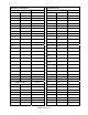
Transmitter Serial Number: ______________ Software Revision: __________
Basic Config As Left Output Config (continued) As Left
Sensor S/N 4-20mA Ch2 Output Sel
Pipe Size ID / Wall Power Sel
Size/Sched Low End
OD / Wall High End
Pipe Material
Out of Range
Fluid Properties Specific Bravity Overrange Rail
SOS (ft/sec) 4mA Trim
Viscosity (Pa s) 20mA Trim
Pressure Pulse Multiplier
Temperature Width (ms)
Pressure Sel
Lowcut
Temperature Sel Output Sel
Altitude Alarm Control Warning
Calibration C0 Critical
C1 Manual Clear
C2
Alarm Warn
Thresh
FLW Min / Max
Flow Direction GVF Min / Max
Op Mode
Alarm Crit
Thresh
FLW Min / Max
Set Date / Time GVF Min / Max
Flow Damping State
Time Constant
Flow Noise Filt State
Magnitude
Flow Spike Filt State
Output Config As Left
Length
4-20mA Ch1 Output Sel Percent
Power Sel GVF Damping State
Low End Time Constant
High End GVF Noise Filt State
Out of Range Magnitude
Overrange Rail GVF Spike Filt State
4mA Trim Length
20mA Trim Delta