
User Manual
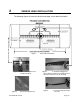


Table of Contents
1 INTRODUCTION................................................................................................................1-1
2 SENSOR HEAD INSTALLATION ......................................................................................2-1
2.1 Process Pipe Cleaning and Marking .........................................................................2-2
2.2 Sensor Band Installation............................................................................................2-2
3 TRANSMITTER STARTUP................................................................................................3-1
3.1 Flow Tab....................................................................................................................3-1
3.2 Sensor Tab................................................................................................................3-1
List of Figures
Figure 1 Sensor Band Installation ........................................................................................2-1
Figure 2 Sensor Band Spacer Tool Installed on Bands........................................................2-1
Figure 3 Sensor Band Spacer Tool ......................................................................................2-1
Figure 4 “Y” Connector Plugged into Sensor Band connectors............................................2-1
Figure 5 “Y” Connector Plug Assembly Close-up.................................................................2-1
List of Tables
Table 1 3-1 Sensor Spacing…………………………………………………………………………….
P/N 21080-01 Rev 02 Page i