
Owner's manual


5 CONTROL DRAWINGS
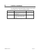
The control drawings define how the Zone 2 hardware can be installed
into hazardous areas. Refer to the following drawings:
Control Drawing System Reference Annex
20907-01C System including TB8-xx-xx-xx-03
Transmitter and SH-xxx-xx-xA-xxx-03
Sensor Head
Annex B
20908-01C Transmitter TB8-xx-xx-xx-04
Transmitter and separately certified
Sensor Head (with separate Control
Drawing)
Annex C
Table 1 Control Drawings
20909-01C Rev 04 Page 5-1