SUPPLEMENT TO INSTALLATION & STARTUP MANUAL: PROCEDURE FOR ELEVATED TEMPERATURE SENSOR HEAD INSTALLATION CiDRA Corporate Services Tel. 203-265-0035 50 Barnes Park North Fax. 203-294-4211 Wallingford, CT 06492 www.cidra.
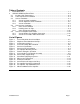
Table of Contents 1 2 INTRODUCTION................................................................................................................1-1 SENSOR HEAD INSTALLATION ......................................................................................2-2 2.1 Caution: High Temperatures ......................................................................................2-2 2.2 Tools Required For Installation ..................................................................................2-2 2.
1 INTRODUCTION This manual is intended to be a supplement to the SONARtrac® Process Monitoring System Installation & Startup Manuals. The information contained in this supplement pertains only to the Elevated Temperature Sensor Head Assembly. The Installation Manual should be read and understood prior to use of this manual. The Elevated Temperature Sensor Head is rated for use in General Purpose (non-hazardous) locations.
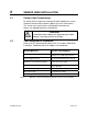
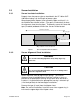
2 SENSOR HEAD INSTALLATION 2.1 Caution: High Temperatures Be careful when installing or removing the high temperature system. Incidental contact with the process pipe may cause serious burns. The sensor cover and fasteners may become extremely hot. Always use appropriate gloves and clothing. WARNING Potential burn hazard. Always wear appropriate gloves when installing or removing system from hot pipes. 2.
2.3 Sensor Installation 2.3.1 Sensor Insulator Installation Properly clean the process pipe as described in the VF-100 or GVF100 Manual along a 36 inch length of process pipe. Wrap the polyimide (Kapton) sheet around the pipe such that it is in the middle of the cleaned section. (The goal is to electrically insulate the alignment sheet from the pipe.) Temporarily secure the sheet with tape (if needed) outboard of where the sensors will be located.
Note: Wires #9 and #10 on the alignment sheet are used for grounding and temperature.
2.3.3 Sensor Installation Slightly bend the alignment tabs on the sensor band alignment sheet upward. These will serve to align the sensors during installation. Wrap the sensor bands around the alignment sheet. Align the edge of the sensor band with the alignment tabs on the alignment sheet. IMPORTANT: The alignment tabs on the alignment sheet are not symmetrical. Install the sensors on the side of the tab shown in Figure 2 above.
Remove the springs from the alignment sheet Bundle the individual sensor wires and wires #9 and #10 together and attach them to the alignment sheet using the tabs provided using a blue Tefzel® wire tie (Tefzel® can withstand high temperature).
2.4 Sensor Cover Installation 2.4.1 Cover Seal Installation Note: The seals to be installed on each cover half must seal on each other when the cover halves are assembled. Also, the crossing seals (start and stop ends) must be on opposite sides of the cover when installed. Remove a short length of the adhesive backing covering on the joint seal strip to expose the adhesive.
Repeat the seal installation on the opposite cover half. Note: Ensure the seals are installed to mirror each other as they must seal on each other during cover installation. Also, the crossing seals must be on opposite sides of the covers when they are installed. Seals must be one continuous length on each cover half.
2.4.2 Installing Cover on Pipe Remove the pre-amplifier housing cover from the upper cover assembly. Disconnect external connector cable assembly from preamplifier assembly. Remove the four screws holding the pre-amplifier assembly in place. Remove the pre-amplifier and place it in a secure location so it will not be damaged.
For horizontal pipe installations, install the cover half with the preamplifier box over the sensor band such that it is centered on the band and over the sensor band cables (allows for maximum sensor cable length). Ensure the cables are accessible. Install the lower cover half and temporarily clamp the upper and lower cover halves in place using spring clamps (or equivalent). Important: Do not allow the cover end seals to touch any part of the sensor array including the polyamide insulation.
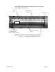
Install 5/16”–18 cover bolts fitted with a washer and lock washer in each cover bolt hole numbered 1 – 16 in the following figure. Tighten the bolts gradually per the tightening sequence given in the following figure so that the flanges remain essentially parallel. Bring halves together evenly until most or the entire gap is removed. Maximum allowable gap is 0.10”. Install ¼”-20 bolts with nuts, washers and lock washers in holes numbered 17 – 20.
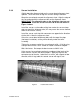
2.4.3 Cover End Seal Installation Un-spool a length of adhesive backed seal and wrap it around the pipe. Overlap the length of seal by about 1.5 inches and then cut it. Repeat for the opposite end of the cover. Figure 12 Measure & Cut End Seal Peel the backing on the seal strip to expose the adhesive strip. Start installing the sealant about ½-inches before the center bolt hole on the top of the cover.
Repeat this installation procedure on the opposite end of the cover. Install the cover end seal compression rings so that they overlap the cover flange seam. The double pair of bolt holes in the end seal compression rings will align with the corresponding double threaded holes in the cover halves. NOTE: If the end seal compression rings do not have a double pair o bolt holes as shown, align the end seam of the compression rings between the two closely spaced tapped holes on the end of the cover.
2.5 Sensor Pre-Amplifier Connections 2.5.1 Sensor Band to Pre-Amplifier Connection Carefully feed the eight sensor wires and wires #9 and #10 from the sensor band through the slot in the sensor band feed through. Reinstall the feed-through in the pre-amplifier housing. Figure 15 Pre-amplifier Housing Feed-through Reinstall the fiberglass insulation in the pre-amplifier housing and route the sensor band wires on top of the insulation.
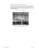
WARNING Discharge each sensor per user manual instructions just prior to connecting sensors to preamp. Failure to do so may result in damage to preamp!! Starting with sensor #1, discharge that sensor by attaching it to the sensor shorting plug. Insert the sensor connector into the mating connector (connector #1) mounted on the bottom of the preamplifier module. Repeat for the remaining 9 wires.
2.5.2 Sensor to Transmitter Cable Connection Install the sensor cover to transmitter cable connector. Terminate the individual sensor to transmitter cable conductors in the transmitter per the Installation Manual. This completes installation of the high temperature sensor head. Refer to the SONARtracTM VF-100 user manual for transmitter installation and start-up instructions.
CiDRA Corporate Services 50 Barnes Park North Wallingford, CT 06492 (In U.S.): 877-cidra77 Tel: 203-265-0035 Fax: 203-294-4211 Visit CiDRA Online at: www.cidra.com CiDRA Corporate Services Tel. 203-265-0035 50 Barnes Park North Fax. 203-294-4211 Wallingford, CT 06492 www.cidra.