
User`s guide


5
CHAPTER 2 JUMPER SETTINGS
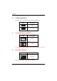
2.1 JUMPER PRESENTATION
Pins 1 and 2 are shorted with a jumper cap.
1 2 3
Pins 2 and 3 are shorted with a jumper cap.
1 2 3
The jumper is shorted when the jumper cap is placed over the
two
pins of the jumper.
The jumper is opened when the cap is removed from jumper.
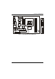
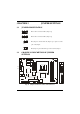
2.2 GRAPHICAL DESCRIPTION OF JUMPER
SETTINGS
KBMS1
USB/LAN
COM1
COM2
V-Video
S-Video
VGA
GAME1
KBMS1
USB1
L IN E L INE MIC
OUT IN IN
12V Conn.
FAN3
JBAT1
J12
FAN1
FAN2
ATX POWER
FDD1
AGP
IDE1
IDE2
JCDIN1
J18
SW1
SW2
VOL
4
0
-
p
i
n
C
o
n
n
40-pin Conn
SPK LINE MIC
OUT IN IN
Fig. 2.1 Jumper /Connector Location of the mainboard