
User`s guide

7
CHAPTER 3 CONNECTOR
CONFIGURATION
Once the mainboard has been fastened into system case, the next step is to connect the internal
cables. The internal cables are wire leads with plastic female connectors that attach to the
connectors. The mainboard connectors have the various numbers of pins and are the contact
points between the mainboard and other parts of the computer.
Refer to Fig. 2.1 for the location of the connectors.
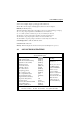
3.1 U1 – SOCKET478
U1 is the Socket478 CPU socket which can support Intel Pentium 4 processor.
3.2 FAN CONNECTORS
FAN1, FAN2, FAN3 are fan connectors of case or CPU.
J18 is a +12V Case FAN Connector.
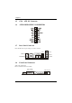
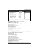
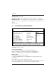
3.3 J12 – MULTIPLE FUNCTION JUMPER
J12 is a front panel multi-function jumper. The pin definition is as following figure.
1
+
+
-
NC
NC
NC
POWER
LED
HDD LED
POWER
SWITCH
RESET
3.4 JCDIN1 – CD-IN CONNECTOR