CFI-S86 High Performance Socket478B Motherboard User’s Guide I
Edition 1.01 © 2002 CHYANG FUN INDUSTRY CO., LTD. P/N: 155100-8970 WARNING To make the system work normally, please ensure JBAT1 of the mainboard is set as below. Refer to Fig. 2.1 in this manual for the location JBAT1. JBAT1 1 2 3 If JBAT1 is shorted to 2-3, no CMOS data can be retained. CAUTION The motherboard is an electrostatic sensitive device. Don’t open or handle except at a staticfree workstation. If you use 1.
PC, AT, PC-DOS, OS/2 and Presentation Manager are trademarks of IBM Corporation. UNIX is the trademark of AT&T. All other brand and product names are trademarks or registered trademarks of their respective companies. The information presented in this publication has been carefully checked for reliability; however, no responsibility is assumed for inaccuracies, whereas, specification is subjected to change without notice.
CONTENTS CHAPTER 1 INTRODUCTION1 1 CHAPTER 2 2.1 2.2 2.3 2.4 2.5 JUMPER SETTINGS Jumper Presentation Graphical Description of Jumper Settings Clear CMOS Data CPU Frequency Setting Factory Setting 3 3 3 4 4 4 CHAPTER 3 3.1 3.2 3.3 3.4 3.5 3.6 3.7 3.8 CONNECTOR CONFIGURATION U1 - Socket478 FAN Connectors J12 - Multiple Function Jumper JCDIN1 - CD-IN Connector CN4 - ATX 12V Connector ATX Power Supply Connector Rear Panel Connectors Front Panel Connectors 5 5 5 5 5 5 6 6 6 CHAPTER 4 4.1 4.2 4.3 4.4 4.
CHAPTER 1 INTRODUCTION Preface CFI-S86 is a 6-layers, Flex-ATX form factor, high-performance Socket478 motherboard. The system core logic is based on VIA P4M266 Chipsets. It is integrated with NEC uPD720100AGM USB 2.0 controller and Realtek RTL8100B Ethernet controller. Features CPU: ?? Support Intel Socket 478 Pentium 4 processor Chipset: ?? VIA P4M266 chipsets ?? Winbond W83627HF LPC controller ?? Realtek RTL8100B Ethernet controller ?? NEC uPD720100AGM USB 2.
Chapter 1 Ethernet: ?? Realtek RTL8100B 10/100Base-T Ethernet controller ?? Full-Duplex supported ?? WFM 2.0 compliant I/O Interface: ?? Winbond W83627HF LPC controller ?? Two enhanced PCI IDE channels which support up to 4 IDE devices with ATA-133 transfers up to 133MB/sec ?? Build in FDC supports 1.2M/1.44M/2.
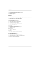
Connector Configuration ATX POWER KBMS1 COM2 KBMS1 MPGA478B NEC USB 2.0 USB/LAN 40-pin Conn DIMM1 S-Video GAME1 USB1 DIMM2 VT1621 VGA V-Video ID E2 W83627HF ID E1 RTL8100B VOL VIA8233 VIA P4M266 SPK LINE MIC OUT IN IN AC97 CODEC PCI 39SF020A BATTERY IrDA AGP L IN E L INE MIC OUT IN IN COM1 FDD1 40-pin Conn Fig. 1.
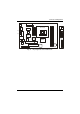
CHAPTER 2 2.1 JUMPER SETTINGS JUMPER PRESENTATION Pins 1 and 2 are shorted with a jumper cap. 1 2 3 1 2 3 Pins 2 and 3 are shorted with a jumper cap. The jumper is shorted when the jumper cap is placed over the two pins of the jumper. The jumper is opened when the cap is removed from jumper. GRAPHICAL DESCRIPTION OF JUMPER SETTINGS J18 KBMS1 FAN3 ATX POWER 12V Conn. COM2 KBMS1 USB1 VGA 40-pin Conn ID E2 FAN1 V-Video ID E1 COM1 FDD1 S-Video GAME1 2.
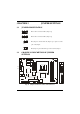
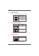
Chapter 2 2.3 CLEAR CMOS DATA JBAT1 is used to clear the CMOS Data in the RTC (build in ICH chip). JBAT1 Description Normal 1 Clear CMOS 1 2.3 CPU FREQUENCY SETTING SW2 4 3 2 Description 1 133MHz 5 6 7 8 4 3 2 1 100MHz 5 6 7 8 Note: P4M266 only support 100MHz * 4 Front Side Bus, SW2 must set at [3,6]. 2.4 FACTORY SETTING SW1 8 7 6 Description 5 SB Default 1 2 3 4 Note: SW1 is SB default setting, cannot be changed.
CHAPTER 3 CONNECTOR CONFIGURATION Once the mainboard has been fastened into system case, the next step is to connect the internal cables. The internal cables are wire leads with plastic female connectors that attach to the connectors. The mainboard connectors have the various numbers of pins and are the contact points between the mainboard and other parts of the computer. Refer to Fig. 2.1 for the location of the connectors. 3.
Chapter 3 3.5 CN4 – ATX 12V Connector 3.6 ATX POWER SUPPLY CONNECTOR 1 3.7 11 Rear Panel Connector CN1 and CN2 is the V-port and S-port of Video connector. LAN MOUSE COM KEYBOARD COM VGA MIC IN LINE IN SPK OUT V-Port S-Port USB 3.8 Front Panel Connector VOL is the volume knob. IrDA is an infrared transceiver module.
CHAPTER 4 4.1 AWARD BIOS DESCRIPTION ENTERING SETUP Power on the computer, when the following message briefly appears at the bottom of the screen during the POST (Power On Self Test), press key or simultaneously press the + + keys, to enter the AWARD BIOS CMOS Setup Utility. Press to enter SETUP Once you have entered, the Main Menu (Fig. 4.1) appears on the screen. The main menu allows you to select from eleven setup functions and two exit choices.
Chapter 4 4.2 STANDARD CMOS FEATURES SETUP Use the arrow keys to highlight the item, and then use the or to select the value desired in each item. Phoenix – AwardBIOS CMOS Setup Utility Standard CMOS Features Date (mm:dd:yy) Time (hh:mm:ss) ? ? ? ? Tue. Jan 01 2002 11:23:33 IDE Primary Master IDE Primary Slave IDE Secondary Master IDE Secondary Slave Item Help Menu Level ? Drive A Drive B [1.44M, 3.5 in.
Award BIOS Description CGA 40: Color Graphic Adapter, powering up in 40-column mode. CGA 80: Color Graphic Adapter, powering up in 80-column mode. MONO: Monochrome adapter, including high-resolution monochrome adapters. Halt On [All, But Keyboard] This field determines whether the system will stop if an error is detected during powering up. All errors: Stop and prompt whenever the BIOS detect a non-fatal error. No errors: The system boot will not stop for any error that may be detected.
Chapter 4 Virus warning: Allows you to choose the VIRUS warning feature for IDE hard disk boot sector protection. If it is enabled and someone attempt to write data into the sector, BIOS will show a warning message on screen and alarm beep. Enabled, Disabled CPU L1 & L2 Cache Enabled, Disabled CPU L2 Cache ECC Checking Enabled, Disabled Quick Power On Self Test: Allows the system to skip some tests while booting. Disabled is Normal POST.
Award BIOS Description ? DRAM Clock/Drive Control ? AGP & P2P Bridge Control ? CPU & PCI Bus Control Memory Hole System BIOS Cacheable Video RAM Cacheable Delay Prior to Thermal VGA Share Memory Size FB Address Conversion FB Page Close Prediction [Press Enter] [Press Enter] [Press Enter] [Disabled] [Disabled] [Disabled] [16 Min] [32M] [Enabled] [Enabled] Item Help Menu Level ? ??? ? :Move Enter:Select +/-/PU/PD:Value F10:Save ESC:Exit F1:General Help F5: Previous Values F6: Fail - Save Defaults F7: Opti
Chapter 4 System BIOS Cacheable: Besides conventional memory, the system BIOS area is also cacheable. Enabled, Disabled: Video RAM Cacheable: Besides conventional memory, video RAM area is also cacheable.
Award BIOS Description 4.
Chapter 4 Init Display First PCI Slot, AGP. USB Keyboard Support: Support USB Keyboard under DOS status. Disabled, Enabled IDE HDD Block Mode: . If your IDE hard drive supports block mode, select Enabled for automatic detection of the optimal number of block read/writes per sector the drive can support. Enabled, Disabled. 4.
Award BIOS Description Video Off Option Suspend -> Off, MODEM Use IRQ, Always On Video Off Method V/H SYNC+Blank: In addition to Blank Screen, BIOS will also turn off the V-SYNC & H – SYNC signals from VGA card to monitor. DPMS Support: This function is enabled only for VGA cards supporting DPMS. Blank Screen: The system BIOS will only blank off the screen when disabling video. Note: When the green monitor does not detect the V/H-SYNC signals, the electron gun will be turned off.
Chapter 4 18
Award BIOS Description 4.
Chapter 4 4.8 PC HEALTH STATUS Phoenix – AwardBIOS CMOS Setup Utility PC Health Status CPU Warning Temperature [Disabled] Item Help Current System Temp.
Award BIOS Description Menu Level ? ??? ? :Move Enter:Select +/-/PU/PD:Value F10:Save ESC:Exit F1:General Help F5: Previous Values F6: Fail - Save Defaults F7: Optimized Defaults CPU CLOCK Ratio: Selects the multiplication of processor core frequency. If a Ratio locked processor installed, this item will be hidden. This item is only for users who understand all the CPU parameters, i.e. system bus frequency, “66MHz” and multiplication of processor core frequency for system bus frequency “x3, x3.5, x4, x4.
Chapter 4 will be prompted for the password only when you enter BIOS Setup. Supervisor Password has higher priority than User Password. You can use Supervisor Password when booting the system or entering BIOS Setup to modify all settings. Also you can use User Password when booting the system or entering BIOS Setup but can not modify any setting if Supervisor Password is enabled.
Award BIOS Description 4.11 EXIT SETUP Save & Exit Setup After finish modifying the values, choose this item to save the changes to the CMOS RAM. A confirmation message will appear, type “Y” and press Enter to save and exit Setup. Exit Without Saving If you do not want to save the changes, choose this item to exit Setup without saving changes. A confirmation message will appear, type “Y” and press Enter to save and exit Setup. 4.
APPENDIX A QUICK GUIDE The table below summaries the functions and settings of each jumper of the motherboard. Function Jumper Settings Normal JBAT1 1-2 Clear JBAT1 2-3 133 MHz SW1.2, SW2.3 Open 100 MHz SW1.2, SW2.