2013 OWNER’S MANUAL 200 Convertible
VEHICLES SOLD IN CANADA With respect to any Vehicles Sold in Canada, the name Chrysler Group LLC shall be deemed to be deleted and the name Chrysler Canada Inc. used in substitution therefore. DRIVING AND ALCOHOL Drunken driving is one of the most frequent causes of accidents. This manual illustrates and describes the operation of features and equipment that are either standard or optional on this vehicle.
SECTION TABLE OF CONTENTS PAGE 1 INTRODUCTION . . . . . . . . . . . . . . . . . . . . . . . . . . . . . . . . . . . . . . . . . . . . . . . . . . . . . . . . . . . . . 3 1 2 THINGS TO KNOW BEFORE STARTING YOUR VEHICLE . . . . . . . . . . . . . . . . . . . . . . . . . . . . . 9 2 3 UNDERSTANDING THE FEATURES OF YOUR VEHICLE . . . . . . . . . . . . . . . . . . . . . . . . . . . . . 97 3 4 UNDERSTANDING YOUR INSTRUMENT PANEL . . . . . . . . . . . . . . . . . . . . . . . . . . . . . . . . . .
INTRODUCTION CONTENTS 䡵 INTRODUCTION . . . . . . . . . . . . . . . . . . . . . . . .4 䡵 VEHICLE IDENTIFICATION NUMBER . . . . . . . .6 䡵 HOW TO USE THIS MANUAL . . . . . . . . . . . . . .4 䡵 VEHICLE MODIFICATIONS/ALTERATIONS . . . .7 䡵 WARNINGS AND CAUTIONS . . . . . . . . . . . . . .
4 INTRODUCTION When it comes to service, remember that your authorized dealer knows your vehicle best, has factory-trained techCongratulations on selecting your new Chrysler Group nicians and genuine MOPAR威 parts, and cares about LLC vehicle. Be assured that it represents precision your satisfaction. workmanship, distinctive styling, and high quality - all essentials that are traditional to our vehicles.
INTRODUCTION 5 1
6 INTRODUCTION WARNINGS AND CAUTIONS This Owners Manual contains WARNINGS against operating procedures that could result in a collision or bodily injury. It also contains CAUTIONS against procedures that could result in damage to your vehicle. If you do not read this entire Owners Manual, you may miss important information. Observe all Warnings and Cautions.
INTRODUCTION 7 VEHICLE MODIFICATIONS/ALTERATIONS WARNING! Any modifications or alterations to this vehicle could seriously affect its roadworthiness and safety and may lead to a collision resulting in serious injury or death. Stamped VIN Location NOTE: It is illegal to remove or alter the VIN.
THINGS TO KNOW BEFORE STARTING YOUR VEHICLE 2 CONTENTS 䡵 A WORD ABOUT YOUR KEYS . . . . . . . . . . . . .12 ▫ To Arm The System . . . . . . . . . . . . . . . . . . . . .19 ▫ Ignition Key Removal . . . . . . . . . . . . . . . . . . .12 ▫ To Disarm The System . . . . . . . . . . . . . . . . . . .20 ▫ Key-In-Ignition Reminder . . . . . . . . . . . . . . . .15 䡵 ILLUMINATED ENTRY — IF EQUIPPED . . . . . .21 䡵 SENTRY KEY威 . . . . . . . . . . . . . . . . . . . . . . . . .15 䡵 REMOTE KEYLESS ENTRY (RKE) . . .
10 THINGS TO KNOW BEFORE STARTING YOUR VEHICLE ▫ Programming Additional Transmitters. . . . . . . .26 䡵 TRUNK SAFETY WARNING. . . . . . . . . . . . . . . .39 ▫ Battery Replacement . . . . . . . . . . . . . . . . . . . .26 ▫ Trunk Internal Emergency Release . . . . . . . . . .39 ▫ General Information . . . . . . . . . . . . . . . . . . . .27 䡵 OCCUPANT RESTRAINTS . . . . . . . . . . . . . . . .40 䡵 REMOTE STARTING SYSTEM — IF EQUIPPED . . . . . . . . . . . . . . . . . . . . . . . . . .
THINGS TO KNOW BEFORE STARTING YOUR VEHICLE 11 ▫ Seat Belts And Pregnant Women . . . . . . . . . . .56 䡵 ENGINE BREAK-IN RECOMMENDATIONS . . . .90 ▫ Seat Belt Extender . . . . . . . . . . . . . . . . . . . . .56 䡵 SAFETY TIPS . . . . . . . . . . . . . . . . . . . . . . . . . .91 ▫ Supplemental Restraint System (SRS) — Air Bags . . . . . . . . . . . . . . . . . . . . . . . . . . . .57 ▫ Air Bag Deployment Sensors And Controls . . . .61 ▫ Event Data Recorder (EDR) . . . . . . . . . . . . . . .
12 THINGS TO KNOW BEFORE STARTING YOUR VEHICLE A WORD ABOUT YOUR KEYS The authorized dealer that sold you your new vehicle has the key code numbers for your vehicle locks. These numbers can be used to order duplicate keys from your authorized dealer. Ask your authorized dealer for these numbers and keep them in a safe place. You can insert the double-sided keys into the locks with either side up. Vehicle Key Ignition Key Removal Place the shift lever in PARK.
THINGS TO KNOW BEFORE STARTING YOUR VEHICLE 13 NOTE: • If you try to remove the key before you place the shift lever into PARK, the key may become trapped temporarily in the ignition switch lock cylinder. If this occurs, place the shift lever in PARK, rotate the key to the right slightly, then remove the key as described. If a malfunction occurs, the system will trap the key in the ignition switch lock cylinder to warn you that this safety feature is inoperable.
14 THINGS TO KNOW BEFORE STARTING YOUR VEHICLE • For vehicles equipped with the Electronic Vehicle Information Center (EVIC), the power window switches, radio, hands–free system (if equipped), and power outlets will remain active for up to 10 minutes after the ignition switch is turned to the LOCK position. Opening either front door will cancel this feature. The time for this feature is programmable.
THINGS TO KNOW BEFORE STARTING YOUR VEHICLE 15 The system uses ignition keys which have an embedded electronic chip (transponder) to prevent unauthorized Opening the driver’s door when the key is in the ignition vehicle operation. Therefore, only keys that are prosounds a chime signal to remind you to remove the key. grammed to the vehicle can be used to start and operate NOTE: the vehicle.
16 THINGS TO KNOW BEFORE STARTING YOUR VEHICLE an invalid key to start the engine. Either of these conditions will result in the engine being shut off after two seconds. CAUTION! (Continued) Use of these systems may result in vehicle starting problems and loss of security protection.
THINGS TO KNOW BEFORE STARTING YOUR VEHICLE 17 authorized dealer or by using the Customer Key Pro- 2. Insert the first valid key into the ignition switch. Turn the ignition switch to the ON/RUN position for at gramming procedure. This procedure consists of proleast three seconds, but no longer than 15 seconds. gramming a blank key to the vehicle electronics. A blank Then, turn the ignition switch to the LOCK position key is one which has never been programmed. and remove the first key.
18 THINGS TO KNOW BEFORE STARTING YOUR VEHICLE The new Sentry Key威 is programmed. The Remote • This device must accept any interference that may be received, including interference that may cause undeKeyless Entry (RKE) transmitter will also be prosired operation. grammed during this procedure. Repeat this procedure to program up to eight keys.
THINGS TO KNOW BEFORE STARTING YOUR VEHICLE 19 Rearming The System If something triggers the alarm, and no action is taken to disarm it, the Vehicle Security Alarm will turn off the horn after three minutes, turn off all of the visual signals after 15 minutes, and then the Vehicle Security Alarm will rearm itself. To Arm The System 3. The Vehicle Security Light in the instrument cluster will flash for 16 seconds. This shows that the Vehicle Security Alarm is arming.
20 THINGS TO KNOW BEFORE STARTING YOUR VEHICLE of the previously described arming sequences has occurred, the Vehicle Security Alarm will arm regardless of Either press the UNLOCK button on the RKE transmitter whether you are in the vehicle or not. If you remain in the or insert a valid Sentry Key威 into the ignition lock vehicle and open a door, the alarm will sound. If this cylinder and turn the key to the ON/START position. occurs, disarm the Vehicle Security Alarm.
THINGS TO KNOW BEFORE STARTING YOUR VEHICLE 21 ILLUMINATED ENTRY — IF EQUIPPED NOTE: The courtesy lights will turn on when you press the • The front courtesy overhead console and door courunlock button on the Remote Keyless Entry (RKE) transtesy lights will turn on if the dimmer control is in the mitter or open any door. ⬙Dome ON⬙ position (extreme top position). This feature also turns on the approach lighting in the • The Illuminated Entry system will not operate if the outside mirrors (if equipped).
22 THINGS TO KNOW BEFORE STARTING YOUR VEHICLE NOTE: To Unlock The Doors • The line of transmission must not be blocked with Press and release the UNLOCK button on the RKE transmitter once to unlock the driver’s door or twice to metal objects when using the RKE transmitter. unlock both doors. The turn signal lights will flash to • Inserting the key into the ignition switch disables all acknowledge the unlock signal. The Illuminated Entry buttons on the RKE transmitter.
THINGS TO KNOW BEFORE STARTING YOUR VEHICLE 23 • For vehicles not equipped with the EVIC, perform the NOTE: If there is no key in the ignition switch, pressing following procedure: the LOCK button on the RKE transmitter while you are inside the vehicle will activate the Vehicle Security Alarm 1. Press and hold the LOCK button on a programmed System. Opening a door with the Vehicle Security Alarm RKE transmitter for at least four seconds, but not activated will cause the alarm to sound.
24 THINGS TO KNOW BEFORE STARTING YOUR VEHICLE • For vehicles not equipped with the EVIC, perform the NOTE: If there is no key in the ignition switch, pressing following procedure: the LOCK button on the RKE transmitter while you are in the vehicle will activate the Vehicle Security Alarm. 1. Press and hold the UNLOCK button on a programmed Opening a door with the Vehicle Security Alarm actiRKE transmitter for at least four seconds, but not vated will cause the alarm to sound.
THINGS TO KNOW BEFORE STARTING YOUR VEHICLE 25 1. Press the LOCK button on a programmed RKE transmitter for at least four seconds, but not longer than 10 Press and release the LOCK button on the RKE transmitseconds. Then, press the PANIC button while still ter to lock both doors. The turn signal lights will flash holding the LOCK button. and the horn will chirp once to acknowledge the lock signal. 2. Release both buttons at the same time. To Lock The Doors Sound Horn With Lock 3.
26 THINGS TO KNOW BEFORE STARTING YOUR VEHICLE NOTE: You may need to be close to the vehicle when using the RKE transmitter to turn off the Panic Alarm due Refer to “Convertible Top Operation” under “Underto the Radio Frequency (RF) noises emitted by the standing The Features Of Your Vehicle” for further inforsystem. mation. Programming Additional Transmitters To Unlatch The Trunk Convertible Top Operation Button — If Equipped Refer to Sentry Key威 “Customer Key Programming.
THINGS TO KNOW BEFORE STARTING YOUR VEHICLE 27 1. With the RKE transmitter buttons facing down, use a 2. Remove and replace the battery. Avoid touching the flat blade tool to pry the two halves of the RKE new battery with your fingers. Skin oils may cause transmitter apart. Make sure not to damage the seal battery deterioration. If you touch a battery, clean it during removal. with rubbing alcohol. 3. To assemble the RKE transmitter case, snap the two halves together.
28 THINGS TO KNOW BEFORE STARTING YOUR VEHICLE NOTE: Changes or modifications not expressly ap- NOTE: proved by the party responsible for compliance could • The vehicle must be equipped with an automatic void the user’s authority to operate the equipment. transmission to be equipped with Remote Start. If your RKE transmitter fails to operate from a normal • Obstructions between the vehicle and the Key Fob may distance, check for these two conditions: reduce this range. 1.
THINGS TO KNOW BEFORE STARTING YOUR VEHICLE 29 • Ignition key removed from ignition switch • Battery at an acceptable charge level Remote Start Abort Message On Electronic Vehicle Information Center (EVIC) — If Equipped The following messages will display in the EVIC if the vehicle fails to remote start or exits remote start prema• System not disabled from previous remote start event turely: • RKE PANIC button not pressed • Vehicle theft alarm not active WARNING! • Do not start or run an engine in a clo
30 THINGS TO KNOW BEFORE STARTING YOUR VEHICLE To Enter Remote Start Mode • If an engine fault is present the vehicle will start and then shut down 10 seconds later. Press and release the REMOTE START button on the RKE transmitter twice within five seconds. The vehicle doors will lock, the parking lights will flash and the horn will chirp twice (if programmed). Then, the engine will start and the vehicle will remain in the Remote Start mode for a 15-minute cycle.
THINGS TO KNOW BEFORE STARTING YOUR VEHICLE 31 NOTE: To avoid unintentional shut downs, the system DOOR LOCKS will disable the one-time press of the remote start button Manual Door Locks for two seconds after receiving a valid remote start To lock each door, push the door lock knob on each door request. trim panel downward. To unlock each door, pull the To Exit Remote Start Mode And Drive The Vehicle inside door handle.
32 THINGS TO KNOW BEFORE STARTING YOUR VEHICLE If the door lock knob is down when you shut the door, the door will lock. Make sure the keys are not inside the vehicle before closing the door. WARNING! • For personal security and safety in the event of an collision, lock the vehicle doors as you drive as well as when you park and leave the vehicle. • When leaving the vehicle, always remove the key fob from the ignition and lock your vehicle.
THINGS TO KNOW BEFORE STARTING YOUR VEHICLE 33 auto door lock feature can be enabled or disabled by your authorized dealer. Please see your authorized dealer for service. Auto Unlock On Exit The doors will unlock automatically on vehicles with power door locks if: 1. The Automatic Unlock Doors On Exit feature is enabled. 2. The transaxle was in gear and the vehicle speed returned to 0 mph (0 km/h). Power Door Lock Switch Automatic Door Locks — If Equipped 3. The transaxle is in NEUTRAL or PARK. 4.
34 THINGS TO KNOW BEFORE STARTING YOUR VEHICLE 4. A single chime will indicate the completion of the programming. The Automatic Unlock Doors On Exit feature can be enabled or disabled as follows: NOTE: This feature will not be functional until the vehicle has been driven and the shift lever returned to the • For vehicles equipped with the Electronic Vehicle Information Center (EVIC), refer to “Electronic Vehicle PARK position.
THINGS TO KNOW BEFORE STARTING YOUR VEHICLE 35 NOTE: • If a fluttering noise is heard from the rear seat belts while driving with the windows down, safely bring the vehicle to a stop and buckle the rear seat belts over the empty seats. This will keep tension on the seat belts and remove the fluttering condition. WARNING! Power Window Switches Never leave children in a vehicle, with the keys in the ignition switch.
36 THINGS TO KNOW BEFORE STARTING YOUR VEHICLE to its full up position after closing the door. This action will remain active for 45 seconds after the ignition switch allows the door to open without resistance and prevents is turned to the LOCK position. Opening either door will cancel this feature. window and top seal damage. Auto Window Down — If Equipped The front window controls on the driver and passenger door trim panels have an Auto-Down feature.
THINGS TO KNOW BEFORE STARTING YOUR VEHICLE 37 button (setting it in the down position). To enable the window control, press and release the window LOCK 2. Press and hold the Power Top Switch in the Close button again (setting it in the up position). direction. Once the Power Top becomes fully closed, all four windows will start closing. 1. Lower all four windows to the full open position. 3. Continue to hold the Power Top Switch an additional two seconds after the windows are fully closed. 4.
38 THINGS TO KNOW BEFORE STARTING YOUR VEHICLE Wind Buffeting Wind buffeting can be described as the perception of pressure on the ears or a helicopter-type sound in the ears. Your vehicle may exhibit wind buffeting with one window down in certain open or partially open positions. This is a normal occurrence and can be minimized. If the buffeting occurs with one window open, then open both windows together to minimize the buffeting.
THINGS TO KNOW BEFORE STARTING YOUR VEHICLE 39 With the ignition switch in the ON/RUN position, the TRUNK SAFETY WARNING word “dECK” will display in the odometer indicating the trunk is open. The odometer display will reappear once WARNING! the trunk is closed or if the trip button is pressed.
40 THINGS TO KNOW BEFORE STARTING YOUR VEHICLE trunk, the trunk can be simply opened by pulling on the • Three-point lap and shoulder belts for all seating positions glow-in-the-dark handle attached to the trunk latching mechanism.
THINGS TO KNOW BEFORE STARTING YOUR VEHICLE 41 seat belt webbing into position by extending the belt Here are some simple steps you can take to minimize the all the way out and then adjusting the belt to the risk of harm from a deploying air bag: desired length to restrain a child seat or secure a large 1. Children 12 years old and under should always ride item in a seat buckled up in a rear seat. Please pay close attention to the information in this section.
42 THINGS TO KNOW BEFORE STARTING YOUR VEHICLE children to slide the shoulder belt behind them or under 5. If the air bag system in this vehicle needs to be their arm. modified to accommodate a disabled person, contact the Customer Center. Phone numbers are provided If a child from 1 to 12 years old (not in a rear facing child under ⴖIf You Need Assistanceⴖ. seat) must ride in the front passenger seat, move the seat as far back as possible and use the proper child restraint.
THINGS TO KNOW BEFORE STARTING YOUR VEHICLE 43 WARNING! (Continued) • Being too close to the steering wheel or instrument panel during Advanced Front Air Bag deployment could cause serious injury, including death. Air Bags need room to inflate. Sit back, comfortably extending your arms to reach the steering wheel or instrument panel. • Seat-Mounted Side Air Bags (SAB) need room to inflate. Do not lean against the door or window. Sit upright in the center of the seat.
44 THINGS TO KNOW BEFORE STARTING YOUR VEHICLE WARNING! WARNING! (Continued) • Be sure everyone in your vehicle is in a seat and using a seat belt properly. • It is dangerous to ride in a cargo area, inside or outside of a vehicle. In a collision, people riding in these areas are more likely to be seriously injured or killed. • Wearing a seat belt incorrectly is dangerous. Seat belts are designed to go around the large bones of your body.
THINGS TO KNOW BEFORE STARTING YOUR VEHICLE 45 2 Pulling Out The Latch Plate 3. When the belt is long enough to fit, insert the latch plate into the buckle until you hear a “click.
46 THINGS TO KNOW BEFORE STARTING YOUR VEHICLE WARNING! WARNING! (Continued) • A belt that is buckled into the wrong buckle will not protect you properly. The lap portion could ride too high on your body, possibly causing internal injuries. Always buckle your belt into the buckle nearest you. • A belt that is loose will not protect you properly. In a sudden stop you could move too far forward, increasing the possibility of injury. Wear your seat belt snugly.
THINGS TO KNOW BEFORE STARTING YOUR VEHICLE 47 WARNING! Positioning The Lap Belt • A lap belt worn too high can increase the risk of injury in a collision. The belt forces won’t be at the strong hip and pelvic bones, but across your abdomen. Always wear the lap part of your seat belt as low as possible and keep it snug. • A twisted belt may not protect you properly. In a collision, it could even cut into you. Be sure the belt is straight.
48 THINGS TO KNOW BEFORE STARTING YOUR VEHICLE 6. To release the belt, push the red button on the buckle. 1. Position the latch plate as close as possible to the anchor point. The belt will automatically retract to its stowed position. If necessary, slide the latch plate down the 2. At about 6 to 12 in (15 to 30 cm) above the latch plate, webbing to allow the belt to retract fully. grasp and twist the belt webbing 180° to create a fold that begins immediately above the latch plate.
THINGS TO KNOW BEFORE STARTING YOUR VEHICLE 49 Restraints” section. The chart below defines the type of out only the amount of webbing necessary to comfortably wrap around the occupant’s mid-section. Slide the feature for each seating position. latch plate into the buckle until you hear a ⬙click.⬙ Driver Center Passenger Automatic Locking Retractor Mode (ALR) — If First Row N/A N/A ALR Equipped Second Row ALR N/A ALR In this mode, the shoulder belt is automatically pre• N/A — Not Applicable locked.
50 THINGS TO KNOW BEFORE STARTING YOUR VEHICLE How To Engage The Automatic Locking Mode 1. Buckle the combination lap and shoulder belt. 2. Grasp the shoulder portion and pull downward until the entire belt is extracted. 3. Allow the belt to retract. As the belt retracts, you will hear a clicking sound. This indicates the safety belt is now in the Automatic Locking Mode.
THINGS TO KNOW BEFORE STARTING YOUR VEHICLE 51 Seat Belt Pretensioners Supplemental Active Head Restraints (AHR) — If The seat belts for both front seating positions are Equipped equipped with pretensioning devices that are designed to These head restraints are passive, deployable comporemove slack from the seat belt in the event of a collision.
52 THINGS TO KNOW BEFORE STARTING YOUR VEHICLE This system is designed to help prevent or reduce the extent of injuries to the driver and front passenger in certain types of rear impacts. NOTE: The Active Head Restraints (AHR) may or may not deploy in the event of a front or side impact. However if during a front impact, a secondary rear impact occurs, the AHR may deploy based on the severity and type of the impact.
THINGS TO KNOW BEFORE STARTING YOUR VEHICLE 53 CAUTION! 1. Grasp the deployed AHR from the rear seat. All occupants, including the driver, should not operate a vehicle or sit in a vehicle’s seat until the head restraints are placed in their proper positions in order to minimize the risk of neck injury in the event of a collision.
54 THINGS TO KNOW BEFORE STARTING YOUR VEHICLE 3. Pull down then rearward towards the rear of the vehicle then down to engage the locking mechanism. 3 — Final Downward Movement To Engage Locking Mechanism 1 — Downward Movement 2 — Rearward Movement 4. The AHR front soft foam and trim half should lock into the back decorative plastic half.
THINGS TO KNOW BEFORE STARTING YOUR VEHICLE 55 • For safety reasons, have the Active Head Restraints checked by a qualified specialist at an authorized dealer. Enhanced Seat Belt Use Reminder System (BeltAlert姞) AHR In Reset Position NOTE: BeltAlert威 is a feature intended to remind the driver and front passenger (if equipped with front passenger BeltAlert威) to fasten their seat belts. The feature is active whenever the ignition is on.
56 THINGS TO KNOW BEFORE STARTING YOUR VEHICLE Light remains illuminated until the respective seat belts are fastened. The driver should instruct all other occupants to fasten their seat belts. If a front seat belt is unbuckled while traveling at speeds greater than 5 mph (8 km/h), BeltAlert威 will provide both audio and visual notification. The front passenger seat BeltAlert威 is not active when the front passenger seat is unoccupied.
THINGS TO KNOW BEFORE STARTING YOUR VEHICLE 57 existing belt is not long enough. When it is not required, instrument panel, above the glove compartment. The words SRS AIRBAG are embossed on the air bag covers. remove the extender, and store it. WARNING! Using a seat belt extender when not needed can increase the risk of injury in a collision. Only use when the seat belt is not long enough when it is worn low and snug, and in the recommended seating positions. Remove and store the extender when not needed.
58 THINGS TO KNOW BEFORE STARTING YOUR VEHICLE NOTE: These air bags are certified to the new Federal protection for an occupant during a side impact. The regulations for Advanced Air Bags. SABs are located in the outboard side of the front seats. The Advanced Front Air Bags have a multistage inflator NOTE: design.
THINGS TO KNOW BEFORE STARTING YOUR VEHICLE 59 • Driver Advanced Front Air Bag • Passenger Advanced Front Air Bag • Supplemental Seat-Mounted Side Air Bags (SAB) • Front and Side Impact Sensors • Front Seat Belt Pretensioners, Seat Belt Buckle Switch, and Seat Track Position Sensors Advanced Front Air Bag Features The Advanced Front Air Bag system has multistage driver and front passenger air bags.
60 THINGS TO KNOW BEFORE STARTING YOUR VEHICLE WARNING! (Continued) • Do not drill, cut or tamper with the knee bolster in any way. • Do not mount any accessories to the knee bolster such as alarm lights, stereos, citizen band radios, etc. Supplemental Seat-Mounted Side Air Bags (SAB) Supplemental Seat-Mounted Side Air Bags (SAB) may provide enhanced protection to help protect an occupant during a side impact. The SAB is marked with an air bag label sewn into the outboard side of the front seats.
THINGS TO KNOW BEFORE STARTING YOUR VEHICLE 61 WARNING! Do not use accessory seat covers or place objects between you and the side air bags; the performance could be adversely affected and/or objects could be pushed into you, causing serious injury. Air Bag Deployment Sensors And Controls Occupant Restraint Controller (ORC) The ORC is part of a Federally regulated safety system required for this vehicle.
62 THINGS TO KNOW BEFORE STARTING YOUR VEHICLE The Advanced Front Air Bags will not deploy in all frontal collisions, including some that may produce substantial vehicle damage — for example, some pole collisions, truck underrides, and angle offset collisions. On the other hand, depending on the type and location of impact, Advanced Front Air Bags may deploy in crashes with little vehicle front-end damage but that produce a severe initial deceleration.
THINGS TO KNOW BEFORE STARTING YOUR VEHICLE 63 It also includes diagnostics that will illuminate the instrument cluster Air Bag Warning Light if a malfunction is noted that could affect the air bag system. The diagnostics also record the nature of the malfunction. WARNING! Ignoring the Air Bag Warning Light in your instrument panel could mean you won’t have the air bags to protect you in a collision.
64 THINGS TO KNOW BEFORE STARTING YOUR VEHICLE Supplemental Seat-Mounted Side Air Bag (SAB) Inflator Units Front And Side Impact Sensors In front and side impacts, impact sensors can aid the The Supplemental Seat-Mounted Side Air Bags (SAB) are ORC in determining appropriate response to impact designed to activate only in certain side collisions. events.
THINGS TO KNOW BEFORE STARTING YOUR VEHICLE 65 • Unlock the doors automatically. In order to reset the Enhanced Accident Response System functions after an event, the ignition switch must be changed from IGN ON to IGN OFF. If A Deployment Occurs The Advanced Front Air Bags are designed to deflate immediately after deployment. NOTE: Front and/or side air bags will not deploy in all collisions. This does not mean something is wrong with the air bag system.
66 THINGS TO KNOW BEFORE STARTING YOUR VEHICLE WARNING! Deployed air bags and seat belt pretensioners cannot protect you in another collision. Have the air bags, seat belt pretensioners, and the front seat belt retractor assemblies replaced by an authorized dealer immediately. Also, have the Occupant Restraint Controller System serviced as well. Maintaining Your Air Bag System WARNING! • Modifications to any part of the air bag system could cause it to fail when you need it.
THINGS TO KNOW BEFORE STARTING YOUR VEHICLE 67 WARNING! (Continued) • Do not attempt to modify any part of your air bag system. The air bag may inflate accidentally or may not function properly if modifications are made. Take your vehicle to an authorized dealer for any air bag system service. If your seat, including your trim cover and cushion, needs to be serviced in any way (including removal or loosening/tightening of seat attachment bolts), take the vehicle to your authorized dealer.
68 THINGS TO KNOW BEFORE STARTING YOUR VEHICLE NOTE: If the speedometer, tachometer, or any engine related gauges are not working, the Occupant Restraint Controller (ORC) may also be disabled. The air bags may not be ready to inflate for your protection. Promptly check the fuse block for blown fuses. Refer to the label located on the inside of the fuse block cover for the proper air bag fuses. See your authorized dealer if the fuse is good.
THINGS TO KNOW BEFORE STARTING YOUR VEHICLE 69 To read data recorded by an EDR, special equipment is required, and access to the vehicle or the EDR is needed. In addition to the vehicle manufacturer, other parties, such as law enforcement, that have the special equipment, can read the information if they have access to the vehicle or the EDR. enough for an adult safety belt. Always check the child seat Owner’s Manual to make sure you have the correct seat for your child.
70 THINGS TO KNOW BEFORE STARTING YOUR VEHICLE WARNING! (Continued) hold even an infant on your lap could become so great that you could not hold the child, no matter how strong you are. The child and others could be badly injured. Any child riding in your vehicle should be in a proper restraint for the child’s size.
THINGS TO KNOW BEFORE STARTING YOUR VEHICLE 71 Larger Children Children Too Large for Child Restraints Child Size, Height, Weight or Age Children who have out-grown their forward-facing child restraint, but are too small to properly fit the vehicle’s seat belt Children 12 years old or younger, who have out-grown the height or weight limit of their booster seat Infants And Child Restraints Safety experts recommend that children ride rearwardfacing in the vehicle until they are two years old or until they
72 THINGS TO KNOW BEFORE STARTING YOUR VEHICLE WARNING! • Never place a rear facing infant seat in front of an air bag. A deploying passenger Advanced Front Air Bag can cause death or serious injury to a child 12 years or younger, including a child in a rearward facing infant seat. • Only use a rearward-facing child restraint in a rear seat. Older Children And Child Restraints Children who are two years old or who have outgrown their rear-facing convertible child seat can ride forwardfacing in the vehicle.
THINGS TO KNOW BEFORE STARTING YOUR VEHICLE 73 WARNING! • Improper installation can lead to failure of an infant or child restraint. It could come loose in a collision. The child could be badly injured or killed. Follow the child restraint manufacturer’s directions exactly when installing an infant or child restraint. • When your child restraint is not in use, secure it in the vehicle with the seat belt or LATCH anchorages, or remove it from the vehicle. Do not leave it loose in the vehicle.
74 THINGS TO KNOW BEFORE STARTING YOUR VEHICLE child is using the lap/shoulder belt, check belt fit peri- or neck, move the child closer to the center of the vehicle. odically. A child’s squirming or slouching can move the Never allow a child to put the shoulder belt under an arm belt out of position. If the shoulder belt contacts the face or behind their back.
THINGS TO KNOW BEFORE STARTING YOUR VEHICLE 75 Lower Anchors and Tethers for Children (LATCH) Restraint System Your vehicle is equipped with the child restraint anchorage system called LATCH, which stands for Lower Anchors and Tethers for CHildren. The LATCH system has three vehicle anchor points for installing LATCHequipped child seats. There are two lower anchorages located at the back of the seat cushion where it meets the seatback and one top tether anchorage located behind the seating position.
76 THINGS TO KNOW BEFORE STARTING YOUR VEHICLE LATCH Positions For Installing Child Restraints In This Vehicle Lower Anchorage Symbol 2 anchorages per seating position Top Tether Anchorage Symbol
THINGS TO KNOW BEFORE STARTING YOUR VEHICLE 77 What is the weight limit (child’s weight + weight of the child restraint) for using the LATCH anchorage system to attach the child restraint? 65 lbs (29.
78 THINGS TO KNOW BEFORE STARTING YOUR VEHICLE Can the rear-facing child restraint touch the back of the front passenger seat? Yes Can the head restraints be removed? The child seat may touch the back of the front passenger seat if the child restraint manufacturer also allows contact. See your child restraint owner’s manual for more information.
THINGS TO KNOW BEFORE STARTING YOUR VEHICLE 79 Locating The LATCH Anchorages In addition, there are tether strap anchorages behind each rear seating position. Access ports to the tether anchors are located in the panel between the rear seat and the rear window. The tether anchors are underneath access covers in the carpet covering the back of the seat where you see the tether anchorage symbol.
80 THINGS TO KNOW BEFORE STARTING YOUR VEHICLE anchorage and a way to tighten the connection to the anchorage. Forward-facing child restraints and some rear-facing infant restraints will also be equipped with a tether strap. The tether strap will have a hook at the end to attach to the top tether anchorage and a way to tighten the strap after it is attached to the anchorage.
THINGS TO KNOW BEFORE STARTING YOUR VEHICLE 81 4. Attach the lower hooks or connectors of the child restraint to the lower anchorages in the selected seat1. If the selected seating position has a Switchable Autoing position. matic Locking Retractor (ALR) seat belt, stow the seat belt, following the instructions below. See the section 5. If the child restraint has a tether strap, connect it to the top tether anchorage.
82 THINGS TO KNOW BEFORE STARTING YOUR VEHICLE How To Stow An Unused ALR Seatbelt When using the LATCH attaching system to install a child restraint, stow all ALR seat belts that are not being used by other occupants or being used to secure child restraints. An unused belt could injure a child if they play with it and accidentally lock the seatbelt retractor. Before installing a child restraint using the LATCH system, buckle the seat belt behind the child restraint and out of the child’s reach.
THINGS TO KNOW BEFORE STARTING YOUR VEHICLE 83 Installing Child Restraints Using The Vehicle Seat Belt The seat belts in the passenger seating positions are equipped with either a Switchable Automatic Locking Retractor (ALR) or a cinching latch plate or both. Both types of seat belts are designed to keep the lap portion of the seat belt tight around the child restraint so that it is not necessary to use a locking clip.
84 THINGS TO KNOW BEFORE STARTING YOUR VEHICLE Lap/Shoulder Belt Systems for Installing Child Restraints in this Vehicle
THINGS TO KNOW BEFORE STARTING YOUR VEHICLE 85 What is the weight limit (child’s weight + weight of the child restraint) for using the Tether Anchor with the seat belt to attach a forward facing child restraint? 65 lbs (29.
86 THINGS TO KNOW BEFORE STARTING YOUR VEHICLE 5. To lock the seat belt, pull down on the shoulder part of the belt until you have pulled all the seat belt webbing out of the retractor. Then, allow the webbing to retract Place the child seat in the center of the seating back into the retractor. As the webbing retracts, you position. For some second row seats, you may need to will hear a clicking sound.
THINGS TO KNOW BEFORE STARTING YOUR VEHICLE 87 8. If the child restraint has a top tether strap and the Installing A Child Restraint With A Cinching seating position has a top tether anchorage, connect Latch Plate (CINCH) — If Equipped the tether strap to the anchorage and tighten the tether 1. Place the child seat in the center of the seating strap. Refer to “Lower Anchors and Tethers for Chilposition.
88 THINGS TO KNOW BEFORE STARTING YOUR VEHICLE 5. If the child restraint has a top tether strap and the seating position has a top tether anchorage, connect the tether strap to the anchorage and tighten the tether strap. Refer to “Lower Anchors and Tethers for Children (LATCH) Restraint System” for directions to attach a tether anchor. facing out, away from the child restraint. Repeat steps 4 to 6, above, to complete the installation of the child restraint.
THINGS TO KNOW BEFORE STARTING YOUR VEHICLE 89 3. Push the tether strap and hook (B) through the access 4. Open the access cover (C) on the carpet covering the port and down into the trunk. Route the tether strap to back of the seat and attach the tether strap hook (D) to provide the most direct path from the child seat to the the anchor. anchor. Child Tether Anchor Child Tether Access Port Cover 5. Remove slack in the tether strap according to the child restraint manufacturer’s instructions.
90 THINGS TO KNOW BEFORE STARTING YOUR VEHICLE While cruising, brief full-throttle acceleration within the limits of local traffic laws contributes to a good break-in. Air Bags deploying in the front seat could harm your pet. Wide-open throttle acceleration in low gear can be detriAn unrestrained pet will be thrown about and possibly mental and should be avoided. injured, or injure a passenger during panic braking or in a collision.
THINGS TO KNOW BEFORE STARTING YOUR VEHICLE 91 NOTE: A new engine may consume some oil during its first few thousand miles (kilometers) of operation. This should be considered a normal part of the break-in and not interpreted as an indication of difficulty. SAFETY TIPS Transporting Passengers NEVER TRANSPORT PASSENGERS IN THE CARGO AREA. WARNING! • Do not leave children or animals inside parked vehicles in hot weather. Interior heat build-up may cause serious injury or death.
92 THINGS TO KNOW BEFORE STARTING YOUR VEHICLE WARNING! (Continued) eventually poison you. To avoid breathing (CO), follow these safety tips: • Do not run the engine in a closed garage or in confined areas any longer than needed to move your vehicle in or out of the area. • If you are required to drive with the trunk/liftgate open, make sure that all windows are closed and the climate control BLOWER switch is set at high speed. DO NOT use the recirculation mode.
THINGS TO KNOW BEFORE STARTING YOUR VEHICLE 93 Front seat belt assemblies must be replaced after a collision. Rear seat belt assemblies must be replaced after a collision if they have been damaged (i.e., bent retractor, torn webbing, etc.). If there is any question regarding belt or retractor condition, replace the belt. feel the air directed against the windshield. See your authorized dealer for service if your defroster is inoperable.
94 THINGS TO KNOW BEFORE STARTING YOUR VEHICLE WARNING! (Continued) WARNING! (Continued) • Never place or install floor mats or other floor coverings in the vehicle that cannot be properly secured to prevent them from moving and interfering with the pedals or the ability to control the vehicle. • Never put floor mats or other floor coverings on top of already installed floor mats. Additional floor mats and other coverings will reduce the size of the pedal area and interfere with the pedals.
THINGS TO KNOW BEFORE STARTING YOUR VEHICLE 95 Periodic Safety Checks You Should Make Outside The Vehicle Door Latches Tires Fluid Leaks Examine tires for excessive tread wear and uneven wear patterns. Check for stones, nails, glass, or other objects lodged in the tread or sidewall. Inspect the tread for cuts and cracks. Inspect sidewalls for cuts, cracks and bulges. Check the wheel nuts for tightness. Check the tires (including spare) for proper cold inflation pressure.
UNDERSTANDING THE FEATURES OF YOUR VEHICLE CONTENTS 䡵 CONVERTIBLE TOP OPERATION . . . . . . . . . .101 䡵 MIRRORS . . . . . . . . . . . . . . . . . . . . . . . . . . . .125 ▫ Power Convertible Top Usage Precautions . . . .102 ▫ Inside Day/Night Mirror . . . . . . . . . . . . . . . .125 ▫ Cargo Shield . . . . . . . . . . . . . . . . . . . . . . . . .106 ▫ Automatic Dimming Mirror — If Equipped . . .126 ▫ Power Convertible Top Controls . . . . . . . . . . .108 ▫ Power Mirrors . . . . . . . . . . . . . . .
98 UNDERSTANDING THE FEATURES OF YOUR VEHICLE ▫ Phone Call Features . . . . . . . . . . . . . . . . . . . .139 ▫ Recliner Adjustment . . . . . . . . . . . . . . . . . . .169 ▫ Uconnect™ Phone Features . . . . . . . . . . . . . .142 ▫ Lumbar Support — If Equipped . . . . . . . . . . .170 ▫ Advanced Phone Connectivity . . . . . . . . . . . .147 ▫ Easy Entry System . . . . . . . . . . . . . . . . . . . .170 ▫ Things You Should Know About Your Uconnect™ Phone . . . . . . . . . . . . . . . . . . . . .
UNDERSTANDING THE FEATURES OF YOUR VEHICLE 99 ▫ Headlight Time Delay . . . . . . . . . . . . . . . . . .179 ▫ Windshield Washers . . . . . . . . . . . . . . . . . . .186 ▫ Lights On Reminder . . . . . . . . . . . . . . . . . . .179 ▫ Mist Feature . . . . . . . . . . . . . . . . . . . . . . . . .187 ▫ Turn Signals . . . . . . . . . . . . . . . . . . . . . . . . .180 ▫ Headlights With Wipers Feature (Available With Automatic Headlights Only) . . . . . . . . .187 ▫ Lane Change Assist . . . . . . . . . .
100 UNDERSTANDING THE FEATURES OF YOUR VEHICLE ▫ Before You Begin Programming HomeLink威. . .194 ▫ Front Seat Cupholder . . . . . . . . . . . . . . . . . . .206 ▫ Programming A Rolling Code . . . . . . . . . . . . .194 ▫ Rear Seat Cupholders . . . . . . . . . . . . . . . . . .207 ▫ Programming A Non-Rolling Code . . . . . . . . .196 䡵 STORAGE . . . . . . . . . . . . . . . . . . . . . . . . . . . .208 ▫ Canadian/Gate Operator Programming . . . . . .198 ▫ Glovebox Storage Compartment . . . . . . . . . .
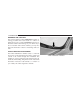
UNDERSTANDING THE FEATURES OF YOUR VEHICLE 101 CONVERTIBLE TOP OPERATION CAUTION! Failure to follow these cautions may cause interior water damage, stains or mildew on the top material: • Avoid high-pressure car washes, as they can damage the top material. Also, increased water pressure may force water past the weather strips. • Remove any standing water from the top and dry the surface before opening it.
102 UNDERSTANDING THE FEATURES OF YOUR VEHICLE When operating the power convertible top, the trunk lid will pivot at the rear of the vehicle, swing open by the rear window, and then pivot backward. This allows room for the top to retract into or unfold from its stowage area in the trunk. Spring-loaded flipper doors, which provide clearance for the linkage, close off notches in the quarter trim panels when the top is down.
UNDERSTANDING THE FEATURES OF YOUR VEHICLE 103 • The Power Top Control Module (PTCM) monitors and controls lowering and raising of the top. A series of micro-switches verify that operations are complete before allowing the next stage of lowering or raising operation. • Opening and closing the top consecutively without the engine running may run the battery down.
104 UNDERSTANDING THE FEATURES OF YOUR VEHICLE CAUTION! CAUTION! (Continued) Before operating the power top: • Always check on top of the tonneau cover area to be sure that it is clear of debris or other items. • Make sure the ambient temperature is above 0°F (-18°C). • Never attempt to lower a frozen convertible top. Wait until the top is thawed before lowering it into the stowage compartment. Lowering a cloth top at temperatures below 32°F (0°C) should be avoided.
UNDERSTANDING THE FEATURES OF YOUR VEHICLE 105 CAUTION! CAUTION! (Continued) • Do not operate the power top with the hydraulic pump valve open. • Do not allow the top to remain in the suspended position. After approximately 10 minutes in the suspended position, the hydraulic pressure will release, which will allow the top and the trunk lid to lower. Pressing the power top switch will cancel this operation. • Always use a normal ice scraper to remove snow or ice from the rear window.
106 UNDERSTANDING THE FEATURES OF YOUR VEHICLE WARNING! WARNING! (Continued) Failure to follow these warnings can result in injuries that are serious or fatal to you, your passengers, and others around you: • Before operating the power top, make sure that no moving parts of the convertible top can injure a person or animal. • Never place any extremities (hands, feet, etc.
UNDERSTANDING THE FEATURES OF YOUR VEHICLE 107 seat the tabs at each end of the cargo shield in the V slots in the trunk liner. Doing so closes a switch that allows top operation. If the switch is not closed, a warning message displays in the instrument cluster to notify the driver. Positioning The Cargo Shield For Top Operation 3 Pull the cargo shield toward you to begin unfolding the panels. Grasp the handle in the center of the outermost (top) panel and raise the cargo shield.
108 UNDERSTANDING THE FEATURES OF YOUR VEHICLE in the trunk trim. Continue folding the upright panel Power Convertible Top Controls forward onto the horizontal panel, then grasp both The power top switch is located on the front of the center panels and lift them to the forward, upright position in console. the trunk. There is also a power top button on the Remote Keyless Entry (RKE) transmitter for remotely lowering the power convertible top.
UNDERSTANDING THE FEATURES OF YOUR VEHICLE 109 Lowering the Power Convertible Top Using The Power Top Switch obstruction and the driver is alerted, the convertible top operation can be stopped by releasing the switch. Using The Remote Keyless Entry Transmitter NOTE: The power top switch will operate when the ignition switch is turned to the ON or ACC position and NOTE: Steps 1 – 3 must be performed within five seconds. when in the power accessory delay. 1.
110 UNDERSTANDING THE FEATURES OF YOUR VEHICLE Raising The Power Convertible Top Manually Closing the power convertible top manually is a complicated and physically demanding procedure, and it reNOTE: The power top switch will operate when the quires a special tool to do so. In the event that you ignition switch is turned to the ON or ACC position and experience a malfunction when operating the power when in the power accessory delay. convertible top: Using The Power Top Switch 1.
UNDERSTANDING THE FEATURES OF YOUR VEHICLE 111 Wind Stop — If Equipped The Wind Stop installs in the backseat area of the vehicle. The Wind Stop will not interfere with power top operation. Therefore, it can remain installed when the top is up. However, when not in use, the Wind Stop folds to allow for convenient storage underneath the cargo shield in the trunk. NOTE: It is recommended that you lower the convertible top before installing or removing the Wind Stop. Installing The Wind Stop 1.
112 UNDERSTANDING THE FEATURES OF YOUR VEHICLE 4. Pivot the small frame (1) away from the large frame (2) 5. Unfold both stems at the rear of the large frame. until the pivot lock (3) engages to lock the two frames in an L shape.
UNDERSTANDING THE FEATURES OF YOUR VEHICLE 113 6. Align and insert the stems into the slot in each trim 7. Align the pins at the front of the large frame with the panel. hole in each trim panel. Slide the pins outward until fully extended into each hole.
114 UNDERSTANDING THE FEATURES OF YOUR VEHICLE Removing And Storing The Wind Stop Power Convertible Top Operation And Warning Reverse the installation procedure to remove, fold, and Messages store the Wind Stop.
UNDERSTANDING THE FEATURES OF YOUR VEHICLE 115 EVIC Message⽧ EVIC Message Display Time⽧ CONVERTIBLE TOP NOT SECURED Until Operation is Complete Odometer Message (< 5 mph [8 km/h]) ⽧⽧ TOP nOT SECUrE Odometer Message Display Time⽧⽧ Until Operation is Complete Odometer Message (> 5 mph [8 km/h]) ⽧⽧ — Odometer Message Display Time⽧⽧ Chime Condition Operator Action Required — — The System is Lowering or Raising the Top — 3
116 UNDERSTANDING THE FEATURES OF YOUR VEHICLE EVIC Message⽧ EVIC Message Display Time⽧ CONVERTIBLE TOP COMPLETE 9 sec. Odometer Message (< 5 mph [8 km/h]) ⽧⽧ TOP DONE Odometer Message Display Time⽧⽧ Display Scrolls for 6 sec.
UNDERSTANDING THE FEATURES OF YOUR VEHICLE 117 EVIC Message⽧ EVIC Message Display Time⽧ SECURE CARGO SHIELD 9 sec. Odometer Message (< 5 mph [8 km/h]) ⽧⽧ SET CARGO SHIELD Odometer Message Display Time⽧⽧ Display Scrolls for 9 sec.
118 UNDERSTANDING THE FEATURES OF YOUR VEHICLE EVIC Message⽧ EVIC Message Display Time⽧ CONVERTIBLE TOP NOT SECURED Until Operation is Complete Odometer Message (< 5 mph [8 km/h]) ⽧⽧ TOP nOT SECUrE Odometer Message Display Time⽧⽧ Until Operation is Complete Odometer Message (> 5 mph [8 km/h]) ⽧⽧ TOP nOT SECUrE Odometer Message Display Time⽧⽧ Chime Condition Operator Action Required Until Operation is Complete Single Chime The System Fails to Complete Operation of Lowering or Raising the Top C
UNDERSTANDING THE FEATURES OF YOUR VEHICLE 119 EVIC Message⽧ EVIC Message Display Time⽧ SPEED TOO HIGH 9 sec. Odometer Message (< 5 mph [8 km/h]) ⽧⽧ SPEED TOO HIGH Odometer Message Display Time⽧⽧ Display Scrolls for 9 sec. Odometer Message (> 5 mph [8 km/h]) ⽧⽧ TOP Odometer Message Display Time⽧⽧ Chime Condition Operator Action Required 6 sec. Single Chime You Are Operating the Power Top at a Vehicle Speed Greater Than 0 mph (0 km/h) The Top Will Not Operate Unless the Vehicle is Stationary.
120 UNDERSTANDING THE FEATURES OF YOUR VEHICLE EVIC Message⽧ EVIC Message Display Time⽧ TRUNK AJAR Continuous Odometer Message (< 5 mph [8 km/h]) ⽧⽧ DECK Odometer Message Display Time⽧⽧ Continuous Odometer Message (> 5 mph [8 km/h]) ⽧⽧ DECK Odometer Message Display Time⽧⽧ Chime Condition Operator Action Required Continuous Single Chime The Trunk Lid is Unlatched or Open The Top Will Not Operate Unless the Trunk Lid is Closed
UNDERSTANDING THE FEATURES OF YOUR VEHICLE 121 EVIC Message⽧ EVIC Message Display Time⽧ CONVERTIBLE TOP MALFUNCTION 6 sec. Odometer Message (< 5 mph [8 km/h]) ⽧⽧ TOP FAIL Odometer Message Display Time⽧⽧ Display Scrolls for 6 Seconds Odometer Message (> 5 mph [8 km/h]) ⽧⽧ TOP Odometer Message Display Time⽧⽧ Chime Condition Operator Action Required 6 sec.
122 UNDERSTANDING THE FEATURES OF YOUR VEHICLE EVIC Message⽧ EVIC Message Display Time⽧ CONVERTIBLE TOP MALFUNCTION Until Fault is No Longer Detected or Repaired Odometer Message (< 5 mph [8 km/h]) ⽧⽧ TOP FAIL Odometer Message Display Time⽧⽧ Display Scrolls until Fault is No Longer Detected or Repaired ⽧ If so equipped. ⽧⽧ For vehicles not equipped with the EVIC.
UNDERSTANDING THE FEATURES OF YOUR VEHICLE 123 ⽧⽧⽧ The PTCM will lockout the power convertible top system if the vehicle charging system is malfunctioning, or the battery is run down, or the hydraulic pump is overheating. In addition, the system prohibits lowering the top when ambient temperature is at 0°F (-18°C) or lower and raising the top when ambient temperature is below -40°F (-40°C).
124 UNDERSTANDING THE FEATURES OF YOUR VEHICLE Emergency Bypass Mode (To Raise The Top Only) CAUTION! (Continued) • Using the Emergency Bypass Mode could potentially damage the convertible top and should only be used to raise the power top to the UP (raised) position when the normal top operation is not functioning.
UNDERSTANDING THE FEATURES OF YOUR VEHICLE 125 MIRRORS Inside Day/Night Mirror A two-point pivot system allows for horizontal and vertical mirror adjustment. Adjust the mirror to center on the view through the rear window. 3 Headlight glare can be reduced by moving the small control under the mirror to the night position (toward the rear of the vehicle). The mirror should be adjusted while set in the day position (toward the windshield).
126 UNDERSTANDING THE FEATURES OF YOUR VEHICLE Automatic Dimming Mirror — If Equipped This mirror automatically adjusts for headlight glare from vehicles behind you. You can turn the feature on or off by pressing the button at the base of the mirror. A light to the left of the button will illuminate to indicate when the dimming feature is activated. The sensor to the right of the button does not illuminate. NOTE: This feature is disabled when the vehicle is moving in reverse.
UNDERSTANDING THE FEATURES OF YOUR VEHICLE 127 When finished, return the knob to the center “O” (Off) The power mirror control is located on the driver’s door position to guard against accidentally moving a mirror position. trim. Power Mirrors 3 Power Mirror Control To adjust a mirror, turn the control toward the left or right mirror positions indicated. Tilt the control in the direction you want the mirror to move.
128 UNDERSTANDING THE FEATURES OF YOUR VEHICLE Adjusting Side View Mirrors WARNING! (Continued) Outside Mirror — Driver Side Adjust the outside mirror to center on the adjacent lane of traffic, with a slight overlap of the view obtained on the inside mirror. Outside Mirror — Passenger Side collide with another vehicle or other object. Use your inside mirror when judging the size or distance of a vehicle seen in the passenger side convex mirror. Some vehicles will not have a convex passenger side mirror.
UNDERSTANDING THE FEATURES OF YOUR VEHICLE 129 window defroster. Refer to “Rear Window Features” in Uconnect™ Phone — IF EQUIPPED “Understanding The Features Of Your Vehicle” for fur- Uconnect™ Phone is a voice-activated, hands-free, inther information. vehicle communications system. Uconnect™ Phone allows you to dial a phone number with your mobile Vanity Mirror — If Equipped phone using simple voice commands (e.g.
130 UNDERSTANDING THE FEATURES OF YOUR VEHICLE • www.jeep.com/uconnect • or call 1–877–855–8400 Uconnect™ Phone allows you to transfer calls between the system and your mobile phone as you enter or exit your vehicle and enables you to mute the system’s microphone for private conversation. The Uconnect™ Phone is driven through your Bluetooth威 “Hands-Free Profile” mobile phone.
UNDERSTANDING THE FEATURES OF YOUR VEHICLE 131 Voice Command Button Operation Actual button location may vary with the ra- Voice commands can be used to operate the Uconnect™ dio. The individual buttons are described in the Phone and to navigate through the Uconnect™ Phone menu structure. Voice commands are required after most “Operation” section. Uconnect™ Phone prompts.
132 UNDERSTANDING THE FEATURES OF YOUR VEHICLE part of the command when you are asked for it. For example, you can use the compound form voice command “Phonebook New Entry”, or you can break the compound form command into two voice commands: “Phonebook” and “New Entry”. Please remember, the Uconnect™ Phone works best when you talk in a normal conversational tone, as if speaking to someone sitting a few feet/meters away from you. Voice Command Tree Refer to “Voice Tree” in this section.
UNDERSTANDING THE FEATURES OF YOUR VEHICLE 133 The following are general phone to Uconnect™ Phone • You will then be asked to give your mobile phone a priority level between one and seven, with one being pairing instructions: the highest priority. You can pair up to seven mobile button to begin. • Press the phones to your Uconnect™ Phone. However, at any given time, only one mobile phone can be in use, • After the “Ready” prompt and the following beep, say “Device Pairing”.
134 UNDERSTANDING THE FEATURES OF YOUR VEHICLE • The system will prompt you to say the number you want to call. • For example, you can say “234-567-8901”. • The Uconnect™ Phone will confirm the phone number and then dial. The number will appear in the display of certain radios. Call By Saying A Name • Press the button to begin. or downloaded phonebook. To learn how to store a name in the phonebook, refer to “Add Names to Your Uconnect™ Phonebook”, in the phonebook.
UNDERSTANDING THE FEATURES OF YOUR VEHICLE 135 • When prompted, enter the number designation (e.g., “Home”, “Work”, “Mobile”, or “Other”). This will allow you to store multiple numbers for each phonebook entry, if desired. Phonebook Download – Automatic Phonebook Transfer From Mobile Phone If equipped and specifically supported by your phone, Uconnect™ Phone automatically downloads names (text • When prompted, recite the phone number for the names) and number entries from your mobile phone’s phonebook.
136 UNDERSTANDING THE FEATURES OF YOUR VEHICLE • A maximum of 1000 entries per phone will be downloaded and updated every time a phone is connected to the Uconnect™ Phone. edited on the mobile phone. The changes are transferred and updated to Uconnect™ Phone on the next phone connection. • Depending on the maximum number of entries down- Edit Uconnect™ Phonebook Entries loaded, there may be a short delay before the latest NOTE: downloaded names can be used.
UNDERSTANDING THE FEATURES OF YOUR VEHICLE 137 • Next, choose the number designation (home, work, • mobile, or other) that you wish to edit. • • When prompted, recite the new phone number for the phonebook entry that you are editing. • After you are finished editing an entry in the phonebook, you will be given the opportunity to edit another entry in the phonebook, call the number you just edited, or return to the main menu. Press the button to begin.
138 UNDERSTANDING THE FEATURES OF YOUR VEHICLE • Note that only the phonebook entry in the current List All Names In The Uconnect™ Phonebook language is deleted. • Press the button to begin. • Automatic downloaded phonebook entries cannot be • After the “Ready” prompt and the following beep, say deleted or edited. “Phonebook List Names”. Delete/Erase “All” Uconnect™ Phonebook Entries • The Uconnect™ Phone will play the names of all the • Press the button to begin.
UNDERSTANDING THE FEATURES OF YOUR VEHICLE 139 Answer Or Reject An Incoming Call — Call The following features can be accessed through the Currently In Progress Uconnect™ Phone if the feature(s) are available on your If a call is currently in progress and you have another mobile service plan.
140 UNDERSTANDING THE FEATURES OF YOUR VEHICLE in progress. To go back to the first call, refer to “Toggling Conference Call Between Calls” in this section. To combine two calls, refer When two calls are in progress (one active and one on to “Conference Call” in this section. button until you hear a hold), press and hold the double beep indicating that the two calls have been Place/Retrieve A Call From Hold joined into one conference call.
UNDERSTANDING THE FEATURES OF YOUR VEHICLE 141 active call is terminated by the phone far end, a call on Call Continuation hold may not become active automatically. This is cell Call continuation is the progression of a phone call on the phone-dependent. To bring the call back from hold, press Uconnect™ Phone after the vehicle ignition key has been button until you hear a single beep. and hold the switched to OFF.
142 UNDERSTANDING THE FEATURES OF YOUR VEHICLE Uconnect™ Phone Features Emergency Assistance Language Selection If you are in an emergency and the mobile phone is reachable: To change the language that the Uconnect™ Phone is using: • Pick up the phone and manually dial the emergency number for your area. button to begin.
UNDERSTANDING THE FEATURES OF YOUR VEHICLE 143 NOTE: • The emergency number dialed is based on the country where the vehicle is purchased (911 for the U.S. and Canada and 060 for Mexico). The number dialed may not be applicable with the available mobile service and area. WARNING! To use your Uconnect™ Phone System in an emergency, your mobile phone must be: • turned on, • paired to the Uconnect™ System, • and have network coverage.
144 UNDERSTANDING THE FEATURES OF YOUR VEHICLE NOTE: Voice Mail Calling • The towing assistance number dialed is based on the country where the vehicle is purchased (1-800-5282069 for the U.S., 1-877-213-4525 for Canada, 55-143454 for Mexico City and 1-800-712-3040 for outside Mexico City in Mexico). Please refer to the 24-Hour “Towing Assistance” coverage details on the DVD in the Warranty Information Booklet and the 24-Hour Towing Assistance references.
UNDERSTANDING THE FEATURES OF YOUR VEHICLE 145 followed by the word “Send”. For example, if required to NOTE: enter your PIN followed with a pound, (3 7 4 6 #), you • You may not hear all of the tones due to mobile phone button and say, “3 7 4 6 # Send”. can press the network configurations. This is normal.
146 UNDERSTANDING THE FEATURES OF YOUR VEHICLE Turning Confirmation Prompts ON/OFF using Uconnect™ Phone. The status is given for network signal strength, phone battery strength, etc. Turning confirmation prompts off will stop the system from confirming your choices (e.g., the Uconnect™ Dialing Using The Mobile Phone Keypad Phone will not repeat a phone number before you dial it). You can dial a phone number with your mobile phone keypad and still use the Uconnect™ Phone (while dialing button to begin.
UNDERSTANDING THE FEATURES OF YOUR VEHICLE 147 from your Uconnect™ Phone paired mobile phone to the Uconnect™ Phone or vice versa, press the button When you mute the Uconnect™ Phone, you will still be and say “Transfer Call”. able to hear the conversation coming from the other party, but the other party will not be able to hear you. In Connect Or Disconnect Link Between The order to mute the Uconnect™ Phone: Uconnect™ Phone And Mobile Phone Mute/Un-Mute (Mute ON/OFF) • Press the button.
148 UNDERSTANDING THE FEATURES OF YOUR VEHICLE • You can also press the button at any time while the list is being played, and then choose the phone that • The Uconnect™ Phone will play the phone names of you wish to select. all paired mobile phones in order from the highest to the lowest priority. To “Select” or “Delete” a paired • The selected phone will be used for the next phone button and say call. If the selected phone is not available, the phone being announced, press the “Select” or “Delete”.
UNDERSTANDING THE FEATURES OF YOUR VEHICLE 149 • You can also press the button at any time while • Press and hold the button for five seconds until the list is being played, and then choose the phone you the session begins, or, wish to delete. button and say the “Voice Training”, • Press the “System Training”, or “Start Voice Training” comThings You Should Know About Your Uconnect™ Phone mand.
150 UNDERSTANDING THE FEATURES OF YOUR VEHICLE Reset • press the button. • Make sure that no one other than you is speaking during a Voice Command period. • Performance is maximized under: • low-to-medium blower setting, • low-to-medium vehicle speed, This will delete all phone pairing, phone book entries, • low road noise, and other settings in all language modes. The System will • smooth road surface, prompt you before resetting to factory settings.
UNDERSTANDING THE FEATURES OF YOUR VEHICLE 151 • Storing names in the phonebook when the vehicle is Far End Audio Performance not in motion is recommended. • Audio quality is maximized under: • It is not recommended to store similar sounding names • low-to-medium blower setting, in the Uconnect™ Phonebook. • low-to-medium vehicle speed, • low road noise, • Phonebook (Downloaded and Uconnect™ Phone Local) name recognition rate is optimized when the • smooth road surface, entries are not similar.
152 UNDERSTANDING THE FEATURES OF YOUR VEHICLE Recent Calls • Uconnect™ Phone will play the new text message for you. If your phone supports “Automatic Phonebook Download”, Uconnect™ Phone can list your Outgoing, Incom- After reading a message, you can “Reply” or “Forward” ing and Missed Calls. the message using Uconnect™ Phone. SMS Send Messages: Uconnect™ Phone can read or send new messages on You can send messages using Uconnect™ Phone. To send your phone.
UNDERSTANDING THE FEATURES OF YOUR VEHICLE 153 Uconnect™ Phone will prompt you to say the name or 11. number of the person you wish to send the message to. 12. List of Preset Messages: 13. 1. Yes 14. 2. No 15. 3. Where are you? 16. 4. I need more direction. 17. 5. L O L 18. 6. Why 19. 7. I love you 20. 8. Call me 9. Call me later 10.
154 UNDERSTANDING THE FEATURES OF YOUR VEHICLE Turn SMS Incoming Announcement ON/OFF Bluetooth威 Communication Link Turning the SMS Incoming Announcement OFF will stop Mobile phones have been found to lose connection to the the system from announcing the new incoming mes- Uconnect™ Phone. When this happens, the connection can generally be reestablished by switching the phone sages. off/on. Your mobile phone is recommended to remain in button. • Press the Bluetooth威 ON mode.
UNDERSTANDING THE FEATURES OF YOUR VEHICLE 155 3
156 UNDERSTANDING THE FEATURES OF YOUR VEHICLE
UNDERSTANDING THE FEATURES OF YOUR VEHICLE 157 3
158 UNDERSTANDING THE FEATURES OF YOUR VEHICLE Primary zero one two three four five six seven eight nine star (*) plus (+) pound (#) add location Voice Commands Alternate (s) Voice Commands Alternate (s) Primary all call cancel confirmation prompts continue delete dial download edit emergency English erase all Espanol Francais
UNDERSTANDING THE FEATURES OF YOUR VEHICLE 159 Primary help home language list names list phones mobile mute mute off new entry no other pair a phone phone pairing phonebook Voice Commands Alternate (s) pairing phone book Voice Commands Alternate (s) Primary previous record again redial return to main menu select phone send set up towing assistance transfer call Uconnect™ Tutorial try again voice training work yes 3 return or main menu select phone settings or phone set up
160 UNDERSTANDING THE FEATURES OF YOUR VEHICLE General Information VOICE COMMAND — IF EQUIPPED This device complies with Part 15 of the FCC rules and Voice Command System Operation RSS 210 of Industry Canada. Operation is subject to the following conditions: This Voice Command system allows you to control your AM, FM radio, satellite radio, disc • Changes or modifications not expressly approved by player, and a memo recorder.
UNDERSTANDING THE FEATURES OF YOUR VEHICLE 161 WARNING! (Continued) laws. All attention should be kept on the roadway ahead. Failure to do so may result in a collision causing serious injury or death. NOTE: At any time, you can say the words “Cancel”, “Help” or “Main Menu”. These commands are universal and can be used from any menu. All other commands can be used depending upon the active application.
162 UNDERSTANDING THE FEATURES OF YOUR VEHICLE Commands Main Menu The Voice Command system understands two types of Start a dialogue by pressing the Voice Command button. You may say “Main Menu” to switch to the commands. Universal commands are available at all times. Local commands are available if the supported main menu. radio mode is active. In this mode, you can say the following commands: Changing the Volume • “Radio” (to switch to the radio mode) 1.
UNDERSTANDING THE FEATURES OF YOUR VEHICLE 163 • “Radio Menu” (to switch to the radio menu) • “Main Menu” (to switch to the main menu) Radio FM • “Channel Number” (to change the channel by its spoken number) • “Next Channel” (to select the next channel) • “Previous Channel” (to select the previous channel) To switch to the FM band, say “FM” or “Radio FM”.
164 UNDERSTANDING THE FEATURES OF YOUR VEHICLE Memo – “Delete” (to delete a memo) To switch to the voice recorder mode, say “Memo”. In • “Delete All” (to delete all memos) this mode, you may say the following commands: Setup • “New Memo” (to record a new memo) — During the To switch to system setup, you may say one of the recording, you may press the Voice Command following: button to stop recording.
UNDERSTANDING THE FEATURES OF YOUR VEHICLE 165 • “Tutorial” 2. Repeat the words and phrases when prompted by Uconnect™ Voice. For best results, the “Voice Train• “Voice Training” ing” session should be completed when the vehicle is parked, engine running, all windows closed, and the NOTE: Keep in mind that you have to press the Voice blower fan switched off. This procedure may be rebutton first and wait for the beep before Command peated with a new user.
166 UNDERSTANDING THE FEATURES OF YOUR VEHICLE WARNING! (Continued) • Do not allow people to ride in any area of your vehicle that is not equipped with seats and seat belts. In a collision, people riding in these areas are more likely to be seriously injured or killed. • Be sure everyone in your vehicle is in a seat and using a seat belt properly. Power Seats The power seat switch is on the outboard side of the seat near the floor.
UNDERSTANDING THE FEATURES OF YOUR VEHICLE 167 WARNING! • Adjusting a seat while driving may be dangerous. Moving a seat while driving could result in loss of control which could cause a collision and serious injury or death. • Seats should be adjusted before fastening the seat belts and while the vehicle is parked. Serious injury or death could result from a poorly adjusted seat belt. • Do not ride with the seatback reclined so that the shoulder belt is no longer resting against your chest.
168 UNDERSTANDING THE FEATURES OF YOUR VEHICLE minutes of continuous operation. If LOW-level heating is selected, the system automatically turns the heater and On some models, the front driver and passenger seats the indicator light OFF after a maximum of 45 minutes of may be equipped with heaters in both the seat cushions continuous operation. and seatbacks. The controls for the front heated seats are located on the center instrument panel area.
UNDERSTANDING THE FEATURES OF YOUR VEHICLE 169 WARNING! (Continued) • Do not place anything on the seat or seatback that insulates against heat, such as a blanket or cushion. This may cause the seat heater to overheat. Sitting in a seat that has been overheated could cause serious burns due to the increased surface temperature of the seat. 3 Recliner Adjustment The recliner control is on the outboard side of the seat. To recline the seat, lean forward slightly and lift the lever.
170 UNDERSTANDING THE FEATURES OF YOUR VEHICLE WARNING! • Adjusting a seat while the vehicle is moving is dangerous. The sudden movement of the seat could cause you to lose control. The seat belt might not be properly adjusted and you could be injured. Adjust the seat only while the vehicle is parked. • Do not ride with the seatback reclined so that the shoulder belt is no longer resting against your chest. In a collision you could slide under the seat belt and be seriously or even fatally injured.
UNDERSTANDING THE FEATURES OF YOUR VEHICLE 171 On the driver seat, pull the lever upward to move the seatback forward. When returning the seatback to its normal position the memory feature restores the seatback recline position to its current setting. Head Restraints Head restraints are designed to reduce the risk of injury by restricting head movement in the event of a rear impact. Head restraints should be adjusted so that the top of the head restraint is located above the top of your ear.
172 UNDERSTANDING THE FEATURES OF YOUR VEHICLE When AHRs deploy during a rear impact, the front half of the head restraint extends forward to minimize the gap vehicle with the head restraints improperly adjusted between the back of the occupant’s head and the AHR. or removed could cause serious injury or death in the This system is designed to help prevent or reduce the event of a collision. extent of injuries to the driver and front passenger in certain types of rear impacts.
UNDERSTANDING THE FEATURES OF YOUR VEHICLE 173 To raise the head restraint, pull upward on the head restraint. To lower the head restraint, press the push button, located at the base of the head restraint, and push downward on the head restraint. For comfort the Active Head Restraints can be tilted forward and rearward. To tilt the head restraint closer to the back of your head, pull forward on the bottom of the head restraint.
174 UNDERSTANDING THE FEATURES OF YOUR VEHICLE • In the event of deployment of an Active Head Restraint, refer to “Occupant Restraints/Resetting Active Head Restraints (AHR)” in “Things to Know Before Starting Your Vehicle” for further information. WARNING! Active Head Restraint (Tilted) NOTE: • The head restraints should only be removed by qualified technicians, for service purposes only. If either of the head restraints require removal, see your authorized dealer.
UNDERSTANDING THE FEATURES OF YOUR VEHICLE 175 WARNING! (Continued) • Active Head Restraints may be deployed if they are struck by an object such as a hand, foot or loose cargo. To avoid accidental deployment of the Active Head Restraint ensure that all cargo is secured, as loose cargo could contact the Active Head Restraint during sudden stops. Failure to follow this warning could cause personal injury if the Active Head Restraint is deployed.
176 UNDERSTANDING THE FEATURES OF YOUR VEHICLE 2. Move to the outside of the vehicle and lift the secondary latch underneath the center front edge of the hood and raise the hood. Hood Prop Rod Before closing the hood, make sure to stow the prop rod in its proper location. Hood Safety Latch Location Use the hood prop rod to secure the hood in the open position. Place the upper end of the prop rod in the hole on the underside of the hood.
UNDERSTANDING THE FEATURES OF YOUR VEHICLE 177 CAUTION! To prevent possible damage, do not slam the hood to close it. Use a firm downward push at the center of the hood to ensure that both latches engage. passing light, fog lights, instrument panel light dimming and turn signals. The multifunction lever is located on the left side of the steering column. 3 WARNING! Be sure the hood is fully latched before driving your vehicle.
178 UNDERSTANDING THE FEATURES OF YOUR VEHICLE Headlights And Parking Lights Automatic Headlights — If Equipped Turn the end of the multifunction lever to the first detent Turning the end of the multifunction lever to the third for parking light operation. Turn to the second detent for detent (AUTO), will activate the automatic headlight headlight operation. system.
UNDERSTANDING THE FEATURES OF YOUR VEHICLE 179 With the engine running and the multifunction lever in Headlight Time Delay the AUTO position, the headlights will turn on and turn There is also a feature that delays turning off the vehicle off based on the surrounding light levels. lights for 30, 60 or 90 seconds after the ignition switch is Headlights With Wipers (Available With Automatic turned OFF.
180 UNDERSTANDING THE FEATURES OF YOUR VEHICLE NOTE: If either light remains on and does not flash, or Move the multifunction lever up or down and the arrows there is a very fast flash rate, check for a defective outside on each side of the instrument cluster flash to show light bulb. If an indicator fails to light when the lever is moved, it would suggest that the indicator bulb is proper operation of the front and rear turn signal lights. defective.
UNDERSTANDING THE FEATURES OF YOUR VEHICLE 181 Flash-To-Pass You can signal another vehicle with your headlights by lightly pulling the multifunction lever toward you. This will turn on the high beam headlights until the lever is released. 3 NOTE: If the multifunction lever is held in the flash-topass position for more than 15 seconds, the high beams will shut off. If this occurs, wait 30 seconds for the next flash-to-pass operation.
182 UNDERSTANDING THE FEATURES OF YOUR VEHICLE Rotate the center portion of the lever upward to the next detent position to brighten the odometer and radio when The front turn signal lamps will turn on as Daytime the parking lights or headlights are on.
UNDERSTANDING THE FEATURES OF YOUR VEHICLE 183 Interior Lights Two courtesy/reading lights are located in the bottom of the rearview mirror. You can turn these lights on and off from the switches in the mirror or from the dimmer control in the multifunction lever. These lights are also controlled automatically by the Illuminated Entry System. 3 Courtesy/Reading Light Switches A courtesy light is also found in the rear of the center console.
184 UNDERSTANDING THE FEATURES OF YOUR VEHICLE Battery Saver Feature To protect the battery, the interior lights will turn off automatically 10 minutes after the ignition switch is moved to the LOCK position. This will occur if the interior lights were switched on manually or are on because a door is open. WINDSHIELD WIPERS AND WASHERS The wipers and washers are operated by a switch on the control lever. The lever is located on the right side of the steering column.
UNDERSTANDING THE FEATURES OF YOUR VEHICLE 185 CAUTION! • Turn the windshield wipers off when driving through an automatic car wash. Damage to the windshield wipers may result if the wiper control is left in any position other than off. • Always remove any buildup of snow that prevents the windshield wiper blades from returning to the off position. If the windshield wiper control is turned off and the blades cannot return to the off position, damage to the wiper motor may occur.
186 UNDERSTANDING THE FEATURES OF YOUR VEHICLE regulate the wipe interval from a minimum of one cycle Windshield Washers every second to a maximum of approximately 18 seconds To use the washer, pull the windshield wiper/washer between cycles. control lever toward you and hold it for as long as washer spray is desired.
UNDERSTANDING THE FEATURES OF YOUR VEHICLE 187 WARNING! (Continued) the windshield during freezing weather, warm the windshield with defroster before and during windshield washer use. Mist Feature Push down on the wiper control lever to activate a single wipe to clear the windshield of road mist or spray from a passing vehicle. As long as the lever is held down, the wipers will continue to operate.
188 UNDERSTANDING THE FEATURES OF YOUR VEHICLE column) is placed in the AUTO position. In addition, the headlights will turn off when the wipers are turned off if they were turned on by this feature. The headlights with wipers feature can be turned on or off through the Electronic Vehicle Information Center (EVIC) — if equipped. Refer to “Electronic Vehicle Information Center (EVIC)/Personal Settings (CustomerProgrammable Features)” in “Understanding Your Instrument Panel” for further information.
UNDERSTANDING THE FEATURES OF YOUR VEHICLE 189 column in position, pull the lever upward until fully engaged. WARNING! Do not adjust the steering column while driving. Adjusting the steering column while driving or driving with the steering column unlocked, could cause the driver to lose control of the vehicle. Be sure the steering column is locked before driving your vehicle. Failure to follow this warning may result in serious injury or death.
190 UNDERSTANDING THE FEATURES OF YOUR VEHICLE NOTE: In order to ensure proper operation, the Electronic Speed Control System has been designed to shut down if multiple Speed Control functions are operated at the same time. If this occurs, the Electronic Speed Control System can be reactivated by pushing the Electronic Speed Control ON/OFF button and resetting the desired vehicle set speed. WARNING! Leaving the Electronic Speed Control system on when not in use is dangerous.
UNDERSTANDING THE FEATURES OF YOUR VEHICLE 191 Pressing the RES (+) button once will result in a 1 mph (1.6 km/h) increase in set speed. Each subsequent tap of A soft tap on the brake pedal, pushing the CANCEL the button results in an increase of 1 mph (1.6 km/h). button, or normal brake pressure while slowing the vehicle will deactivate Electronic Speed Control without To decrease speed while the Electronic Speed Control is erasing the set speed memory. Pressing the ON/OFF set, push the SET (-) button.
192 UNDERSTANDING THE FEATURES OF YOUR VEHICLE Using Electronic Speed Control On Hills GARAGE DOOR OPENER — IF EQUIPPED The transmission may downshift on hills to maintain the HomeLink威 replaces up to three hand-held transmitters vehicle set speed. that operate devices such as garage door openers, motorized gates, lighting or home security systems. The NOTE: The Electronic Speed Control system maintains HomeLink威 unit is powered by your vehicles 12 Volt speed up and down hills.
UNDERSTANDING THE FEATURES OF YOUR VEHICLE 193 3 HomeLink威 Buttons/Overhead Consoles HomeLink威 Buttons/Sunvisor/Headliner NOTE: HomeLink威 is disabled when the Vehicle Security Alarm is active.
194 UNDERSTANDING THE FEATURES OF YOUR VEHICLE Before You Begin Programming HomeLink姞 NOTE: Be sure that your vehicle is parked outside of the garage • Erasing all channels should only be performed when before you begin programming. programming HomeLink威 for the first time. Do not erase channels when programming additional buttons.
UNDERSTANDING THE FEATURES OF YOUR VEHICLE 195 2. Place the hand-held transmitter 1 to 3 in (3 to 8 cm) away from the HomeLink威 button you wish to program while keeping the HomeLink威 indicator light in view. 3. Simultaneously press and hold both the Homelink威 button you want to program and the hand-held transmitter button. Training The Garage Door Opener 1 — Door Opener 2 — Training Button 1. Turn the ignition switch to the ON/RUN position. 4.
196 UNDERSTANDING THE FEATURES OF YOUR VEHICLE 5. At the garage door opener motor (in the garage), locate the “LEARN” or “TRAINING” button. This can usually be found where the hanging antenna wire is attached to the garage door opener/device motor. Firmly press and release the “LEARN” or “TRAINING” button. On some garage door openers/devices there may be a light that blinks when the garage door opener/device is in the LEARN/TRAIN mode.
UNDERSTANDING THE FEATURES OF YOUR VEHICLE 197 1. Turn the ignition switch to the ON/RUN position. 2. Place the hand-held transmitter 1 to 3 in (3 to 8 cm) away from the HomeLink威 button you wish to program while keeping the HomeLink威 indicator light in view. • If the indicator light stays on constantly, programming is complete and the garage door/device should activate when the HomeLink威 button is pressed. • To program the two remaining HomeLink威 buttons, repeat each step for each remaining button.
198 UNDERSTANDING THE FEATURES OF YOUR VEHICLE 2. Place the hand-held transmitter 1 to 3 in (3 to 8 cm) away from the HomeLink威 button you wish to proFor programming transmitters in Canada/United States gram while keeping the HomeLink威 indicator light in that require the transmitter signals to “time-out” after view. several seconds of transmission. Canadian radio frequency laws require transmitter sig- 3.
UNDERSTANDING THE FEATURES OF YOUR VEHICLE 199 3. Without releasing the button proceed with “Canadian/Gate Operator Programming” Step 2 and follow all remaining steps. 5. Press and hold the programmed HomeLink威 button and observe the indicator light. • If the indicator light stays on constantly, programming is complete and the garage door/device should activate when the HomeLink威 button is pressed. • To program the two remaining HomeLink威 buttons, repeat each step for each remaining button.
200 UNDERSTANDING THE FEATURES OF YOUR VEHICLE The HomeLink威 Universal Transceiver is disabled when the Vehicle Security Alarm is active. Troubleshooting Tips If you are having trouble programming HomeLink威, here are some of the most common solutions: • Replace the battery in the original hand-held transmitter. • Press the LEARN button on the Garage Door Opener to complete the training for a Rolling Code.
UNDERSTANDING THE FEATURES OF YOUR VEHICLE 201 General Information NOTE: This device complies with FCC rules Part 15 and Industry • The transmitter has been tested and it complies with Canada RSS-210. Operation is subject to the following FCC and IC rules. Changes or modifications not extwo conditions: pressly approved by the party responsible for compliance could void the user’s authority to operate the 1. This device may not cause harmful interference. device. 2.
202 UNDERSTANDING THE FEATURES OF YOUR VEHICLE ELECTRICAL POWER OUTLETS There are two 12 Volt (13 Amp) electrical power outlets on this vehicle. Both of the power outlets are protected by a fuse. The instrument panel power outlet, located below the climate control knobs, has power available only when the ignition is ON. This power outlet will also operate a conventional cigar lighter unit.
UNDERSTANDING THE FEATURES OF YOUR VEHICLE 203 NOTE: To ensure proper operation a MOPAR威 knob and element must be used. CAUTION! Center Console Power Outlet The center console power outlet is powered directly from the battery (power available at all times). Items plugged into this power outlet may discharge the battery and/or prevent the engine from starting. • Do not exceed the maximum power of 160 Watts (13 Amps) at 12 Volts.
204 UNDERSTANDING THE FEATURES OF YOUR VEHICLE WARNING! To avoid serious injury or death: • Only devices designed for use in this type of outlet should be inserted into any 12 Volt outlet. • Do not touch with wet hands. • Close the lid when not in use and while driving the vehicle. • If this outlet is mishandled, it may cause an electric shock and failure.
UNDERSTANDING THE FEATURES OF YOUR VEHICLE 205 CAUTION! • Many accessories that can be plugged in draw power from the vehicle’s battery, even when not in use (i.e., cellular phones, etc.). Eventually, if plugged in long enough, the vehicle’s battery will discharge sufficiently to degrade battery life and/or prevent the engine from starting. • Accessories that draw higher power (i.e., coolers, vacuum cleaners, lights, etc.) will degrade the battery even more quickly.
206 UNDERSTANDING THE FEATURES OF YOUR VEHICLE CUPHOLDERS Front Seat Cupholder The cupholder in the center console will accommodate either two large size cups or two 20 oz. (.5 L) bottles or cans. The one-piece insert can be removed easily for cleaning. An optional removable ashtray may be located in one of the cupholders.
UNDERSTANDING THE FEATURES OF YOUR VEHICLE 207 Rear Seat Cupholders Cupholders for the rear seat occupants are located in the armrests. Each cupholder is capable of holding up to a 20 oz. (.5 L) bottle or can. Rear Cupholders WARNING! If containers of hot liquid are place in the cupholder, they can spill when the door is closed, burning the occupants. Be careful when closing the doors to avoid injury.
208 UNDERSTANDING THE FEATURES OF YOUR VEHICLE STORAGE Glovebox Storage Compartment The glovebox storage compartment is located on the right side of the instrument panel. To open the glovebox, pull outward on the latch handle located on the front of the glovebox. Glovebox Storage Compartment CONSOLE FEATURES Storage The center console is located between the front driver and passenger seats.
UNDERSTANDING THE FEATURES OF YOUR VEHICLE 209 comfort. The center console can be used for storage and is also equipped with an electrical power outlet. Refer to “Power Outlets” in “Understanding The Feature of Your Vehicle” for further information. 3 Center Console Storage The top compartment holds small items, such as a pen and note pad, while the larger bottom compartment will hold CDs and alike. The bottom compartment also conCenter Console Armrest tains a 12 Volt power outlet.
210 UNDERSTANDING THE FEATURES OF YOUR VEHICLE NOTE: CARGO AREA FEATURES • A notch in the front of the console base allows for use The 60/40 split-folding rear seat provides cargo-carrying of a cellular phone while it is plugged into the power versatility. The seatbacks fold down easily by pulling nylon tabs between the seatbacks and the bolsters. When outlet with the armrest latched down.
UNDERSTANDING THE FEATURES OF YOUR VEHICLE 211 WARNING! (Continued) • The cargo area in the rear of the vehicle (with the rear seatbacks in the locked-up or folded down position) should not be used as a play area by children when the vehicle is in motion. They could be seriously injured in a collision. Children should be seated and using the proper restraint system. • To help protect against personal injury, passengers should not be seated in the rear cargo area.
212 UNDERSTANDING THE FEATURES OF YOUR VEHICLE Ski Pass-Through REAR WINDOW FEATURES There is a ski pass-through door located behind the rear Rear Window Defroster seat armrest that allows longer items, such as snow skis, to be stored in the rear cargo area. Lower the armrest and The rear window defroster button is located on pull downward on the latch to open the ski pass-through the climate control (Mode) knob. Press this button door.
UNDERSTANDING THE FEATURES OF YOUR VEHICLE 213 CAUTION! Failure to follow these cautions can cause damage to the heating elements: • Use care when washing the inside of the rear window. Do not use abrasive window cleaners on the interior surface of the window. Use a soft cloth and a mild washing solution, wiping parallel to the heating elements. Labels can be peeled off after soaking with warm water.
UNDERSTANDING YOUR INSTRUMENT PANEL CONTENTS 䡵 INSTRUMENT PANEL FEATURES. . . . . . . . . . .218 ▫ EVIC Main Menu . . . . . . . . . . . . . . . . . . . . .241 䡵 INSTRUMENT CLUSTER . . . . . . . . . . . . . . . . .219 ▫ Compass Display . . . . . . . . . . . . . . . . . . . . .241 䡵 INSTRUMENT CLUSTER DESCRIPTIONS . . . . .220 ▫ Average Fuel Economy. . . . . . . . . . . . . . . . . .244 䡵 MINI-TRIP COMPUTER — IF EQUIPPED . . . . .235 ▫ Distance To Empty (DTE) . . . . . . . . . . . . . . . .
216 UNDERSTANDING YOUR INSTRUMENT PANEL 䡵 SETTING THE ANALOG CLOCK . . . . . . . . . . .249 䡵 MEDIA CENTER 130 WITH SATELLITE RADIO (SALES CODE RES+RSC) . . . . . . . . . . . . . . . . .259 䡵 MEDIA CENTER 730N/430/430N (RHR/RER/ RBZ/RHB) CD/DVD/HDD/NAV — ▫ Operating Instructions — Radio Mode. . . . . . .259 IF EQUIPPED . . . . . . . . . . . . . . . . . . . . . . . . .249 ▫ Operation Instructions — CD MODE for CD ▫ Operating Instructions (Voice Command System) and MP3 Audio Play . . . . . . . . . . . . . .
UNDERSTANDING YOUR INSTRUMENT PANEL 217 ▫ Controlling The iPod威 Or External USB Device 䡵 CD/DVD DISC MAINTENANCE . . . . . . . . . Using Radio Buttons . . . . . . . . . . . . . . . . . . .278 䡵 RADIO OPERATION AND MOBILE PHONES ▫ Play Mode . . . . . . . . . . . . . . . . . . . . . . . . . .278 䡵 CLIMATE CONTROLS . . . . . . . . . . . . . . . . . ▫ List Or Browse Mode . . . . . . . . . . . . . . . . . . .279 ▫ Manual Heating And Air Conditioning . . . . ▫ Bluetooth Streaming Audio (BTSA) . . . . . . . . .
218 UNDERSTANDING YOUR INSTRUMENT PANEL INSTRUMENT PANEL FEATURES 1 2 3 4 5 — Air Outlet — Side Window Demister Outlet — Instrument Cluster — Ignition Switch — Analog Clock 6 — Radio 7 — Passenger Airbag 8 — Glove Compartment 9 — Heated Seat Switch – If Equipped 10 — Hazard Switch 11 — Storage Compartment 12 — Climate Control 13 — Trunk Release Button 14 — Power Outlet
UNDERSTANDING YOUR INSTRUMENT PANEL 219 INSTRUMENT CLUSTER 4
220 UNDERSTANDING YOUR INSTRUMENT PANEL removes this heat. You can also turn the Temperature control to maximum heat, the Mode control to Floor and 1. Temperature Gauge the Fan control to High. This allows the heater core to act The temperature gauge shows engine coolant tempera- as a supplement to the radiator and aids in removing heat ture. Any reading below the red mark of the gauge shows from the engine cooling system. that the engine cooling system is operating properly. The 2.
UNDERSTANDING YOUR INSTRUMENT PANEL 221 5. Low Fuel Light If jump starting is required, refer to “Jump Starting Procedures” in “What To Do In Emergencies”. When the fuel level drops to approximately 2.0 gallons (7.6 Liters), the fuel symbol will light and 7. Air Bag Warning Light a single chime will sound. This light will turn on for four to eight seconds as a bulb check when the ignition switch is first NOTE: This light will remain on until a minimum of turned to ON/RUN.
222 UNDERSTANDING YOUR INSTRUMENT PANEL If the light comes on and remains on while driving, stop the vehicle and shut off the engine. DO NOT OPERATE When the ignition switch is first turned to ON/ THE VEHICLE UNTIL THE CAUSE IS CORRECTED. RUN, this light will turn on for four to eight seconds as a bulb check. During the bulb check, if The light does not show the quantity of oil in the engine. the driver’s seat belt is unbuckled, a chime will sound.
UNDERSTANDING YOUR INSTRUMENT PANEL 223 shift the transmission into NEUTRAL and idle the vehicle. If the temperature reading does not return to normal, turn the engine off immediately and call for service. Refer to “If Your Engine Overheats” in “What To Do In Emergencies” for further information. The light will remain on until the cause is corrected. NOTE: The light may flash momentarily during sharp cornering maneuvers which change fluid level conditions.
224 UNDERSTANDING YOUR INSTRUMENT PANEL In the event of an EBD failure, the Brake Warning Light 12. Tachometer will turn on along with the ABS Light. Immediate repair The silver area of the scale shows the permissible engine to the ABS system is required. revolutions-per-minute (RPM x 1000) for each gear range. The operation of the Brake Warning Light can be checked Before reaching the red area, ease up on the accelerator to by turning the ignition switch from the OFF position to prevent engine damage.
UNDERSTANDING YOUR INSTRUMENT PANEL 225 correct mileage that the vehicle has been driven. If your odometer needs to be repaired or serviced, the repair technician should leave the odometer reading the same as it was before the repair or service. If s/he cannot do so, then the odometer must be set at zero, and a sticker must be placed in the door jamb stating what the mileage was before the repair or service.
226 UNDERSTANDING YOUR INSTRUMENT PANEL TOP donE . . . . Convertible Top Up/Down Operation Refer to “Convertible Top Operation” in “Understanding Is Complete The Features Of Your Vehicle” for a table that explains how long each message is displayed and the conditions TOP nOT SECUrE . . . Convertible Top Is Not Secured under which each message is displayed. . . . . . . . . . . . . . . . . . . . Low Tire Pressure LoW tirE When the appropriate condition exists, the odometer HOTOIL . . . . . . . . .
UNDERSTANDING YOUR INSTRUMENT PANEL 227 indicator system is duty cycle based, which means the engine oil change interval may fluctuate dependent upon If the vehicle diagnostic system detects a leak or change your personal driving style. in the evaporative system, or the fuel filler cap is loose, improperly installed, or damaged, the words “gASCAP” Unless reset, this message will continue to display each will display in the odometer display area.
228 UNDERSTANDING YOUR INSTRUMENT PANEL NOTE: If the indicator message illuminates when you To reset the trip odometer, first display the trip mileage start the vehicle, the oil change indicator system did not that you want to reset, “Trip A” or “Trip B.” Then push reset. If necessary, repeat this procedure. and hold the button (approximately 2 seconds) until the display resets to 0 miles (kilometers).
UNDERSTANDING YOUR INSTRUMENT PANEL 229 The light will come on when the ignition switch is first 20. Turn Signal Indicators turned on and remain on briefly as a bulb check. This is The left or right arrow will flash with the correnormal. If the light does not come on during starting, sponding exterior turn signal lights when the turn have the system checked by an authorized dealer. signal lever is operated. A chime will sound if the vehicle is 18.
230 UNDERSTANDING YOUR INSTRUMENT PANEL 23. Anti-Lock Brake (ABS) Light — If Equipped should come on. If the light does not come on, have the system inspected by an authorized dealer. This light monitors the ABS. This light will come on when the ignition key is turned to the 24. Electronic Stability Control (ESC) Activation/ ON/RUN position and may stay on for ap- Malfunction Indicator Light — If Equipped proximately three seconds.
UNDERSTANDING YOUR INSTRUMENT PANEL 231 NOTE: 25. Tire Pressure Monitoring Telltale Light The “ESC Off Indicator Light” and the “ESC Activation/ Malfunction Indicator Light” come on momentarily each time the ignition switch is turned to ON/RUN. Each tire, including the spare (if provided), should be checked monthly when cold and inflated to the inflation pressure recommended by the vehicle manufacturer on the vehicle placard or tire inflation pressure label.
232 UNDERSTANDING YOUR INSTRUMENT PANEL reduces fuel efficiency and tire tread life, and may affect alternate tires or wheels on the vehicle that prevent the TPMS from functioning properly. Always check the the vehicle’s handling and stopping ability.
UNDERSTANDING YOUR INSTRUMENT PANEL 233 26. Malfunction Indicator Light (MIL) The Malfunction Indicator Light (MIL) is part of an onboard diagnostic system called OBD that monitors emissions, engine, and automatic transmission control systems. The light will illuminate when the key is in the ON/RUN position before engine start. If the bulb does not come on when turning the key from LOCK to ON/RUN, have the condition checked promptly.
234 UNDERSTANDING YOUR INSTRUMENT PANEL 27. Transmission Temperature Warning Light — If Equipped WARNING! This light indicates that the transmission fluid If the Transmission Temperature Warning Light is temperature is running hot. This may occur illuminated and you continue operating the vehicle, with severe usage, such as trailer towing.
UNDERSTANDING YOUR INSTRUMENT PANEL 235 MINI-TRIP COMPUTER — IF EQUIPPED Control Buttons The Mini-Trip Computer is located in the instrument cluster and features a driver-interactive trip information and temperature display. NOTE: The system will display the last known outside temperature when starting the vehicle and may need to be driven several minutes before the updated temperature is displayed.
236 UNDERSTANDING YOUR INSTRUMENT PANEL RESET Button Trip B To reset the display shown, turn the ignition switch to the Shows the total distance traveled for Trip B since the last ON position, then press and hold the RESET button reset. located on the steering wheel.
UNDERSTANDING YOUR INSTRUMENT PANEL 237 • Miles To Empty • Low Tire Information (Tire Pressure Monitor System (TPMS) Displays) — if equipped • Timer • Units • System Warnings (Door Ajar, etc.
238 UNDERSTANDING YOUR INSTRUMENT PANEL The system allows the driver to select information by • MENU Button pressing the following buttons mounted on the steering Press and release the MENU button to advance wheel: the display to each of the EVIC Main Menu features. Upon reaching the last item in the Main Menu the EVIC will advance to the first item in the Main Menu with the next MENU button press and release.
UNDERSTANDING YOUR INSTRUMENT PANEL 239 • SELECT Button • RKE (Remote Keyless Entry) Battery Low (with a single chime) Press and release the SELECT Button to accept a selection. The SELECT Button also resets • various Trip Functions.
240 UNDERSTANDING YOUR INSTRUMENT PANEL • Remote start aborted — Hood ajar • Remote start aborted — Trunk ajar • Remote start aborted — Fuel low • Remote start disabled — System fault • Convertible Top Not Secured (with a single chime) • Convertible Top Complete (with a single chime) • Secure Cargo Shield (with a single chime) • Speed Too High (with a single chime) • Convertible Top Malfunction (with a single chime) • Oil Change Required (with a single chime) • Check TPM System (with a single chime) Refer
UNDERSTANDING YOUR INSTRUMENT PANEL 241 1. Turn the ignition switch to the ON position (Do not • Average Fuel Economy start the engine.) • Distance to Empty 2. Fully depress the accelerator pedal slowly three times • Tire Pressure Status display within 10 seconds. • Elapsed Time 3. Turn the ignition switch to the LOCK position. • EVIC Units Selection NOTE: If the indicator message illuminates when you start the vehicle, the oil change indicator system did not • System Status reset.
242 UNDERSTANDING YOUR INSTRUMENT PANEL NOTE: The system will display the last known outside temperature when starting the vehicle and may need to be driven several minutes before the updated temperature is displayed. Engine temperature can also affect the displayed temperature; therefore, temperature readings are not updated when the vehicle is not moving.
UNDERSTANDING YOUR INSTRUMENT PANEL 243 4. Press and release the SELECT button and the “CAL” should be kept away from the top of the instrument panel. This is where the compass module is located and indicator will start flashing. such devices may interfere and cause false compass 5. Drive the vehicle slowly (under 5 mph / 8 km/h), readings. completing one or more circles (in an area free from large metal or metallic objects) until the “CAL” indicator turns off. The compass will now function normally.
244 UNDERSTANDING YOUR INSTRUMENT PANEL To Change Compass Variance: Average Fuel Economy 1. Turn the ignition switch to the ON position. Leave the Shows the average fuel economy since the last reset. Average Fuel Economy can be reset by pressing and shift lever in PARK. holding the SELECT button (as prompted in the EVIC 2. Press and release the MENU button until “Personal display). Upon reset, the history information will be Settings” displays in the EVIC.
UNDERSTANDING YOUR INSTRUMENT PANEL 245 When the DTE value is less than 30 miles (48 km) • If the Tire Pressure System requires service, ⬙Check TPM System⬙ is displayed. Tire PSI is an information estimated driving distance, the DTE display will change only function and cannot be reset. to a text display of ⬙LOW FUEL”. This display will continue until the vehicle runs out of fuel.
246 UNDERSTANDING YOUR INSTRUMENT PANEL EVIC Units Selection (UNITS IN Display) Personal Settings (Customer-Programmable Displays the units used for the Outside Temperature, Features) Average Fuel Economy, Distance to Empty and Tire Personal Settings allows the driver to set and recall Pressure features. Press and Release the SELECT button features when the automatic transaxle is in PARK. to toggle units between ⬙U.S.⬙ and ⬙METRIC⬙.
UNDERSTANDING YOUR INSTRUMENT PANEL 247 Auto Unlock On Exit Flash Lamp with LOCK When ON is selected and the transaxle is in the PARK or NEUTRAL position, all doors will unlock when the driver’s door is opened. To make your selection, press the SELECT button until ON or OFF appears. When ON is selected, the front and rear turn signals will flash when the doors are locked or unlocked with the RKE transmitter. This feature may be selected with or without the Sound Horn with LOCK feature selected.
248 UNDERSTANDING YOUR INSTRUMENT PANEL headlights will also turn off when the wipers are turned off if they were turned on by this feature. To make your selection, press the SELECT button until ON or OFF appears. Illumin. Approach When this feature is selected, the headlights will activate and remain on for up to 90 seconds when the doors are unlocked with the remote keyless entry transmitter.
UNDERSTANDING YOUR INSTRUMENT PANEL 249 SETTING THE ANALOG CLOCK MEDIA CENTER 730N/430/430N (RHR/RER/RBZ/ To set the analog clock, located at the top center of the RHB) CD/DVD/HDD/NAV — IF EQUIPPED instrument panel, press and hold the button in until the NOTE: The sales code is located on the lower right side setting is correct. The clock will adjust slowly at first and of the unit’s faceplate. then quicker the longer the button is held.
250 UNDERSTANDING YOUR INSTRUMENT PANEL MEDIA CENTER 130 (SALES CODE RES) Operating Instructions — Radio Mode NOTE: The radio sales code is located on the lower right NOTE: The ignition switch must be in the ON or ACC side of the radio faceplate. position to operate the radio. Power Switch/Volume Control (Rotary) Push the ON/VOLUME control knob to turn on the radio. Push the ON/VOLUME control knob a second time to turn off the radio.
UNDERSTANDING YOUR INSTRUMENT PANEL 251 3. After adjusting the hours, press the right side TUNE/ SCROLL control knob to set the minutes. The minutes Press and release the SEEK buttons to search for the next will begin to blink. listenable station in AM/FM mode. Press the right switch to seek up and the left switch to seek down. The radio 4. Adjust the minutes using the right side TUNE/ will remain tuned to the new station until you make SCROLL control knob. Press the TUNE/SCROLL conanother selection.
252 UNDERSTANDING YOUR INSTRUMENT PANEL Push the rotary TUNE/SCROLL control knob a fifth time and FADE will display. Turn the TUNE/SCROLL control Push the rotary TUNE/SCROLL control knob and BASS knob to the left or right to adjust the sound level between will display. Turn the TUNE/SCROLL control knob to the front and rear speakers. the right or left to increase or decrease the bass tones.
UNDERSTANDING YOUR INSTRUMENT PANEL 253 SET/RND button, the station will continue to play but DISC Button will not be stored into pushbutton memory. Pressing the DISC button will allow you to switch from You may add a second station to each pushbutton by AM/FM modes to Disc modes. repeating the above procedure with this exception: Press Operation Instructions — CD MODE For CD And the SET/RND button twice and SET 2 will show in the MP3 Audio Play display window.
254 UNDERSTANDING YOUR INSTRUMENT PANEL radio display. If a CD does not go into the slot more than 1.0 in (2.5 cm), a disc may already be loaded and must be ejected before a new disc can be loaded. CAUTION! (Continued) • The RES Media Center is a single CD player. Do not attempt to insert a second CD if one is already loaded. If you insert a disc with the ignition ON and the radio ON, the unit will switch from radio to CD mode and begin to play when you insert the disc.
UNDERSTANDING YOUR INSTRUMENT PANEL 255 SEEK Button AM/FM Button Press the right SEEK button for the next selection on the CD. Press the left SEEK button to return to the beginning of the current selection, or return to the beginning of the previous selection if the CD is within the first second of the current selection. Pressing and holding the SEEK button will allow faster scrolling through the tracks in CD and MP3 modes. Press the button to select either AM or FM mode.
256 UNDERSTANDING YOUR INSTRUMENT PANEL Supported Media (Disc Types) The MP3 file recording media supported by the radio are CDDA, CD-R, CD-RW, MP3, and CDDA+MP3. Supported Medium Formats (File Systems) display the file name and folder name, and will assign a number instead. With a maximum number of files, exceeding 20 folders will result in this display. With 200 files, exceeding 50 folders will result in this display.
UNDERSTANDING YOUR INSTRUMENT PANEL 257 Supported MP3 File Formats The radio will recognize only files with the *.MP3 extension as MP3 files. Non-MP3 files named with the *.MP3 extension may cause playback problems. The radio is designed to recognize the file as an invalid MP3 and will not play the file. MPEG Specification MPEG-1 Audio Layer 3 Sampling Frequency (kHz) 48, 44.
258 UNDERSTANDING YOUR INSTRUMENT PANEL To increase the speed of disc loading, it is recommended to use CD-R media and single-session discs. To create a When a medium containing MP3 data is loaded, the radio checks all files on the medium. If the medium single-session disc, enable the “Disc at Once” option before writing to the disc. contains a lot of folders or files, the radio will take more time to start playing the MP3 files.
UNDERSTANDING YOUR INSTRUMENT PANEL 259 NOTE: The AUX device must be turned on and the device’s volume set to proper level. If the AUX audio is not loud enough, turn the device’s volume up. If the AUX audio sounds distorted, turn the device’s volume down. TIME Button (Auxiliary Mode) Press this button to change the display to time of day. The time of day will display for five seconds (when ignition is OFF).
260 UNDERSTANDING YOUR INSTRUMENT PANEL Power Switch/Volume Control (Rotary) another selection. Holding either button will bypass stations without stopping, until you release it. Push the ON/VOLUME control knob to turn on the radio. Push the ON/VOLUME control knob a second Voice Command System (Radio) — If Equipped time to turn off the radio. Refer to “Voice Command” in “Understanding The Features If Your Vehicle”.
UNDERSTANDING YOUR INSTRUMENT PANEL 261 3. After adjusting the hours, press the right side TUNE/ SCROLL control knob to set the minutes. The minutes Press this button to operate the Uconnect™ Phone feature will begin to blink. (if equipped). Refer to “Uconnect™ Phone” in “Understanding The Features If Your Vehicle”. 4. Adjust the minutes using the right side TUNE/ SCROLL control knob. Press the TUNE/SCROLL conIf your vehicle is not equipped with or this feature is not trol knob to save time change.
262 UNDERSTANDING YOUR INSTRUMENT PANEL Push the rotary TUNE/SCROLL control knob a second time and MID will display. Turn the TUNE/SCROLL Press the INFO button for an RDS station (one with call control knob to the right or left to increase or decrease the letters displayed). The radio will return a Radio Text mid-range tones. message broadcast from an FM station (FM mode only). Push the rotary TUNE/SCROLL control knob a third RW/FF time and TREBLE will display.
UNDERSTANDING YOUR INSTRUMENT PANEL 263 Push the rotary TUNE/SCROLL control knob again to exit setting tone, balance, and fade. MUSIC TYPE Button Pressing this button once will turn on the Music Type mode for five seconds. Pressing the MUSIC TYPE button or turning the TUNE/SCROLL control knob within five seconds will allow the program format type to be selected. Many radio stations do not currently broadcast Music Type information.
264 UNDERSTANDING YOUR INSTRUMENT PANEL Program Type Religious Talk Rock Soft Soft Rock Soft Rhythm and Blues Sports Talk Top 40 Weather 16-Digit Character Display Rel Talk Rock Soft Soft Rck Soft R&B Sports Talk Top 40 Weather If a preset button is activated while in the Music Type (Program Type) mode, the Music Type mode will be exited and the radio will tune to the preset station.
UNDERSTANDING YOUR INSTRUMENT PANEL 265 SET/RND Button — To Set the Pushbutton Memory Every time a preset button is used, a corresponding button number will display. When you are receiving a station that you wish to commit to pushbutton memory, press the SET/RND button. The symbol SET 1 will now show in the display window. Select the button (1–6) you wish to lock onto this station and press and release that button.
266 UNDERSTANDING YOUR INSTRUMENT PANEL • This radio is capable of playing compact discs (CD), recordable compact discs (CD-R), rewritable compact discs (CD-RW), compact discs with MP3 tracks and multisession compact discs with CD and MP3 tracks. Inserting Compact Disc(s) CAUTION! • This CD player will accept 4–3/4 in (12 cm) discs only. The use of other sized discs may damage the CD player mechanism. • Do not use adhesive labels. These labels can peel away and jam the player mechanism.
UNDERSTANDING YOUR INSTRUMENT PANEL 267 A disc can be ejected with the radio and ignition OFF. RW/FF NOTE: Ejecting with the ignition OFF is not allowed on Press and hold FF (Fast Forward) and the CD player will begin to fast forward until FF is released or RW or convertible or soft-top models (if equipped). another CD button is pressed. The RW (Reverse) button SEEK Button works in a similar manner. Press the right SEEK button for the next selection on the AM/FM Button CD.
268 UNDERSTANDING YOUR INSTRUMENT PANEL Notes On Playing MP3 Files • Maximum number of folder levels: 8 The radio can play MP3 files; however, acceptable MP3 • Maximum number of files: 255 file recording media and formats are limited. When • Maximum number of folders. (The radio display of file writing MP3 files, pay attention to the following restricnames and folder names is limited. For large numbers tions.
UNDERSTANDING YOUR INSTRUMENT PANEL 269 CD audio tracks and computer files (including MP3 files). Discs created with an option such as ⬙keep disc open after writing⬙ are most likely multisession discs. The use of multisession for CD audio or MP3 playback may result in longer disc loading times. Supported MP3 File Formats MPEG Specification MPEG-1 Audio Layer 3 Sampling Frequency (kHz) 48, 44.
270 UNDERSTANDING YOUR INSTRUMENT PANEL To increase the speed of disc loading, it is recommended to use CD-R media and single-session discs. To create a When a medium containing MP3 data is loaded, the radio checks all files on the medium. If the medium single-session disc, enable the “Disc at Once” option before writing to the disc. contains a lot of folders or files, the radio will take more time to start playing the MP3 files.
UNDERSTANDING YOUR INSTRUMENT PANEL 271 Press the INFO button once more to return to ⬙elapsed NOTE: The AUX device must be turned on and the device’s volume set to the proper level. If the AUX audio time⬙ priority mode. is not loud enough, turn the device’s volume up. If the Press and hold the INFO button for three seconds or AUX audio sounds distorted, turn the device’s volume more and the radio will display song titles for each file. down.
272 UNDERSTANDING YOUR INSTRUMENT PANEL NOTE: Sirius service is not available in Hawaii and has 1. The Electronic Serial Number/Sirius Identification Number (ESN/SID). limited coverage in Alaska. System Activation 2. Your Vehicle Identification Number. Sirius Satellite Radio service is pre-activated, and you may begin listening immediately to the one year of audio service that is included with the factory-installed satellite radio system in your vehicle.
UNDERSTANDING YOUR INSTRUMENT PANEL 273 Satellite Antenna To ensure optimum reception, do not place items on the roof around the rooftop antenna location. Metal objects placed within the line of sight of the antenna will cause decreased performance. Larger luggage items such as bikes should be placed as far rearward as possible, within the loading design of the rack. Do not place items directly on or above the antenna. • Placing objects over or too close to the antenna can cause signal blockage.
274 UNDERSTANDING YOUR INSTRUMENT PANEL SCAN Button TUNE Control (Rotary) Pressing the SCAN button causes the tuner to search for Turn the rotary TUNE/SCROLL control knob clockwise the next channel, pausing for eight seconds before con- to increase or counterclockwise to decrease the channel. tinuing to the next. To stop the search, press the SCAN MUSIC TYPE Button button a second time. Pressing this button once will turn on the Music Type INFO Button mode for five seconds.
UNDERSTANDING YOUR INSTRUMENT PANEL 275 SETUP Button Pressing the SETUP button allows you to select the following items: • Display Sirius ID number — Press the AUDIO/ SELECT button to display the Sirius ID number. This number is used to activate, deactivate, or change the Sirius subscription. SET Button – To Set the Pushbutton Memory You may add a second channel to each pushbutton by repeating the above procedure with this exception: Press the SET button twice and SET 2 will show in the display window.
276 UNDERSTANDING YOUR INSTRUMENT PANEL iPod姞/USB/MP3 CONTROL — IF EQUIPPED NOTE: NOTE: This section is for sales code RES and REQ/ • If the radio has a USB port, refer to the appropriate REL/RET radios only with Uconnect™. For sales code Uconnect™ Multimedia radio User’s Manual for RBZ/RHB, RHR, RHP, RHW or RB2 touch-screen radio iPod威 or external USB device support capability.
UNDERSTANDING YOUR INSTRUMENT PANEL 277 NOTE: If the audio device battery is completely discharged, it may not communicate with the iPod威/USB/ MP3 control system until a minimum charge is attained. Leaving the audio device connected to the iPod威/USB/ MP3 control system may charge it to the required level.
278 UNDERSTANDING YOUR INSTRUMENT PANEL Controlling The iPod姞 Or External USB Device Using Radio Buttons To get into the iPod威/USB/MP3 control mode and access a connected audio device, either press the “AUX” button on the radio faceplate or press the VR button and say ⬙USB⬙ or ⬙Switch to USB⬙. Once in the iPod威/USB/MP3 control mode, audio tracks (if available from audio device) start playing over the vehicle’s audio system.
UNDERSTANDING YOUR INSTRUMENT PANEL 279 • Use the << SEEK and SEEK>> buttons to jump to the previous or next track. Pressing the SEEK>> button during play mode will jump to the next track in the list, or press the VR button and say ⬙Next or Previous Track⬙. next song. To stop SCAN mode and start playing the desired track, when it is playing the track, press the SCAN button again. During Scan mode, pressing the << SEEK and SEEK>> buttons will select the previous and next tracks.
280 UNDERSTANDING YOUR INSTRUMENT PANEL • Preset 1 – Playlists • TUNE control knob: The TUNE control knob functions in a similar manner as the scroll wheel on the audio • Preset 2 – Artists device or external USB device. • Preset 3 – Albums • Turning it clockwise (forward) and counterclockwise • Preset 4 – Genres (backward) scrolls through the lists, displaying the • Preset 5 – Audiobooks track detail on the radio display.
UNDERSTANDING YOUR INSTRUMENT PANEL 281 track in that list. Not all iPod威 or external USB device sub-menu levels are available on this system. • MUSIC TYPE button: The MUSIC TYPE button is another shortcut button to the genre listing on your audio device. CAUTION! • Leaving the iPod威 or external USB device (or any supported device) anywhere in the vehicle in extreme heat or cold can alter the operation or damage the device. Follow the device manufacturer’s guidelines.
282 UNDERSTANDING YOUR INSTRUMENT PANEL Play Mode Next Track When switched to BTSA mode, some audio devices can start playing music over the vehicle’s audio system, but some devices require the music to be initiated on the device first, then it will get streamed to the Uconnect™ phone system. Seven devices can be paired to the Uconnect™ phone system, but just one can be selected and played.
UNDERSTANDING YOUR INSTRUMENT PANEL 283 STEERING WHEEL AUDIO CONTROLS — IF EQUIPPED The remote sound system controls are located on the rear surface of the steering wheel, at the three and nine o’clock positions. The right-hand rocker switch has a pushbutton in the center, and controls the volume and mode of the sound system. Pressing the top of the rocker switch will increase the volume. Pressing the bottom of the rocker switch will decrease the volume.
284 UNDERSTANDING YOUR INSTRUMENT PANEL Radio Operation CD/DVD DISC MAINTENANCE Pressing the top of the switch will SEEK up for the next To keep a CD/DVD in good condition, take the following listenable station, and pressing the bottom of the switch precautions: will SEEK down for the next listenable station. 1. Handle the disc by its edge; avoid touching the The button located in the center of the left-hand switch surface. will tune to the next preset station that you have pro2.
UNDERSTANDING YOUR INSTRUMENT PANEL 285 NOTE: If you experience difficulty in playing a particular disc, it may be damaged (i.e., scratched, reflective coating removed, a hair, moisture or dew on the disc) oversized, or have protection encoding. Try a known good disc before considering disc player service. CLIMATE CONTROLS The air conditioning and heating system is designed to make you comfortable in all types of weather.
286 UNDERSTANDING YOUR INSTRUMENT PANEL The Manual Temperature Controls consist of a series of Temperature Control outer rotary dials and inner push knobs. Blower Control Rotate this control to regulate the temperature of the air inside the passenger compartment. Rotating the dial left into the blue area of the scale indicates cooler temperatures, while rotating right into the red area indicates warmer temperatures.
UNDERSTANDING YOUR INSTRUMENT PANEL 287 Mode Control (Air Direction) • Bi-Level Air is directed through the panel and floor outlets. Rotate this control to choose from several patterns of air distribution. You can select either a primary mode as identified by the symbols on the control, or a blend of two of these modes. The closer the setting is to a particular symbol, the more air distribution you receive from that mode.
288 UNDERSTANDING YOUR INSTRUMENT PANEL • Defrost NOTE: Air is directed through the windshield and side • Continuous use of the Recirculation mode may make the inside air stuffy and window fogging may occur. window demist outlets. Use this mode with maxiExtended use of this mode is not recommended. mum blower and temperature settings for best windshield and side window defrosting.
UNDERSTANDING YOUR INSTRUMENT PANEL 289 • The A/C can be deselected manually without disturb- • MAX A/C ing the mode control selection. For maximum cooling use the A/C and recirculation • When the ignition switch is turned to the LOCK buttons at the same time. position, the recirculation feature will be cancelled. • ECONOMY MODE Air Conditioning Control Press this button to engage the Air Conditioning. A light will illuminate when the Air Conditioning system is engaged.
290 UNDERSTANDING YOUR INSTRUMENT PANEL Automatic Temperature Control (ATC) — If Equipped Automatic Operation The Automatic Temperature Control system automatically maintains the climate in the cabin of the vehicle at the comfort levels desired by the driver and passenger. Operation of the system is quite simple. 1. Turn the Mode Control knob (on the right) and the Blower Control knob (on the left) to AUTO NOTE: The AUTO position performs best for front seat occupants only.
UNDERSTANDING YOUR INSTRUMENT PANEL 291 2. Dial in the temperature you would like the system to NOTE: maintain by rotating the Temperature Control knob. • The temperature setting can be adjusted at anytime Once the comfort level is selected, the system will without affecting automatic operation. maintain that level automatically using the heating system.
292 UNDERSTANDING YOUR INSTRUMENT PANEL • While operating in AUTO, the system will not automatically sense the presence of fog, mist or ice on the windshield. The defrost mode must be manually selected to clear the windshield and side glass. Manual Operation This system offers a full complement of manual override features, which consist of Blower Preferred Automatic, Mode Preferred Automatic, or Blower and Mode Preferred Automatic.
UNDERSTANDING YOUR INSTRUMENT PANEL 293 4
294 UNDERSTANDING YOUR INSTRUMENT PANEL The operator can override the AUTO mode setting to • Floor change airflow distribution by rotating the Mode Control Air is directed through the floor outlets with a knob (on the right) to one of the following positions. small amount flowing through the defrost and • Panel side window demist outlets. Air is directed through the outlets in the instru- • Mix ment panel. These outlets can be adjusted to direct Air is directed through the floor, defrost, and side airflow.
UNDERSTANDING YOUR INSTRUMENT PANEL 295 • Air Conditioner Control NOTE: Press this button to turn on the air • When the ignition switch is turned to the LOCK position, the recirculation feature will be cancelled. conditioning during manual operation only. When the air conditioning is • In cold weather, use of the Recirculation mode may turned on, cool dehumidified air will lead to excessive window fogging.
296 UNDERSTANDING YOUR INSTRUMENT PANEL • Most of the time, when in Automatic Operation, you can temporarily put the system into Recirculation Mode by pressing the Recirculation button. However, under certain conditions, while in Automatic Mode, the system is blowing air out the defrost vents. When these conditions are present, and the Recirculation button is pressed, the indicator will flash and then turn off. This tells you that you are unable to go into Recirculation Mode at this time.
UNDERSTANDING YOUR INSTRUMENT PANEL 297 adequate system lubrication to minimize the possibility FLOOR, MIX, or DEFROST mode. The air is directed at of compressor damage when the system is started again. the area of the windows through which you view the outside mirrors. Window Fogging Interior fogging on the windshield can be quickly re- Outside Air Intake moved by turning the mode selector to Defrost. The Mix mode can be used to maintain a clear windshield and provide sufficient heating.
298 UNDERSTANDING YOUR INSTRUMENT PANEL Control Setting Suggestions for Various Weather Conditions
STARTING AND OPERATING CONTENTS 䡵 STARTING PROCEDURES . . . . . . . . . . . . . . . .303 ▫ Gear Ranges . . . . . . . . . . . . . . . . . . . . . . . . .316 ▫ Normal Starting. . . . . . . . . . . . . . . . . . . . . . .303 ▫ Six-Speed Automatic Transmission — If Equipped . . . . . . . . . . . . . . . . . . . . . . . . . . .314 ▫ Extreme Cold Weather (Below –20°F Or −29°C) . . . . . . . . . . . . . . . .304 ▫ Gear Ranges . . . . . . . . . . . . . . . . . . . . . . . . .316 ▫ After Starting . . . . . . .
300 STARTING AND OPERATING 䡵 DRIVING THROUGH WATER . . . . . . . . . . . . .324 䡵 TIRE SAFETY INFORMATION . . . . . . . . . . . . .340 ▫ Flowing/Rising Water . . . . . . . . . . . . . . . . . .325 ▫ Tire Markings . . . . . . . . . . . . . . . . . . . . . . . .340 ▫ Shallow Standing Water . . . . . . . . . . . . . . . . .325 ▫ Tire Identification Number (TIN). . . . . . . . . . .343 䡵 POWER STEERING . . . . . . . . . . . . . . . . . . . . .327 ▫ Tire Terminology And Definitions . . . . . . . . . .
STARTING AND OPERATING 301 ▫ Spare Tire Matching Original Equipped Tire And Wheel – If Equipped . . . . . . . . . . . . . . . . . . .355 ▫ Compact Spare Tire – If Equipped . . . . . . . . .355 ▫ Full Size Spare – If Equipped . . . . . . . . . . . . .356 ▫ Limited-Use Spare – If Equipped . . . . . . . . . .356 ▫ Tire Spinning . . . . . . . . . . . . . . . . . . . . . . . .357 ▫ Tread Wear Indicators . . . . . . . . . . . . . . . . . .358 ▫ Life Of Tire . . . . . . . . . . . . . . . . . . . . . . . . .
302 STARTING AND OPERATING ▫ Ethanol Fuel (E-85) . . . . . . . . . . . . . . . . . . . .376 䡵 VEHICLE LOADING . . . . . . . . . . . . . . . . . . . .382 ▫ Fuel Requirements . . . . . . . . . . . . . . . . . . . .376 ▫ Vehicle Certification Label . . . . . . . . . . . . . . .382 ▫ Selection Of Engine Oil For Flexible Fuel Vehicles (E-85) And Gasoline Vehicles . . . . . . .377 ▫ Gross Vehicle Weight Rating (GVWR) . . . . . . .382 ▫ Starting . . . . . . . . . . . . . . . . . . . . . . . . . . . .
STARTING AND OPERATING 303 STARTING PROCEDURES WARNING! (Continued) Before starting your vehicle, adjust your seat, adjust the inside and outside mirrors, fasten your seat belt, and if present, instruct all other occupants to buckle their seat belts. • Do not leave the key fob in or near the vehicle. A child could operate power windows, other controls, or move the vehicle. Normal Starting WARNING! • When leaving the vehicle, always remove the key fob from the ignition and lock your vehicle.
304 STARTING AND OPERATING starter will disengage automatically in 10 seconds. If this occurs, turn the ignition switch to the LOCK position, wait 10 to 15 seconds, then repeat the “Normal Starting” procedure. Extreme Cold Weather (Below –20°F Or −29°C) ENGINE BLOCK HEATER — IF EQUIPPED The engine block heater warms the engine, and permits quicker starts in cold weather. Connect the cord to a standard 110-115 Volt AC electrical outlet with a grounded, three-wire extension cord.
STARTING AND OPERATING 305 AUTOMATIC TRANSMISSION CAUTION! Damage to the transmission may occur if the following precautions are not observed: • Shift into PARK only after the vehicle has come to a complete stop. • Shift into or out of REVERSE only after the vehicle has come to a complete stop and the engine is at idle speed. • Do not shift between PARK, REVERSE, NEUTRAL, or DRIVE when the engine is above idle speed.
306 STARTING AND OPERATING WARNING! (Continued) WARNING! (Continued) • Unintended movement of a vehicle could injure those in and near the vehicle. As with all vehicles, you should never exit a vehicle while the engine is running. Before exiting a vehicle, always apply the parking brake, shift the transmission into PARK, and remove the ignition key. Once the key is removed, the shift lever is locked in PARK, securing the vehicle against unwanted movement.
STARTING AND OPERATING 307 ignition when the ignition is in the LOCK/OFF position, Four-Speed Automatic Transmission — If and once removed, the shift lever is locked in PARK. Equipped NOTE: If a malfunction occurs, the system will trap the key in the ignition switch to warn you that this safety feature is inoperable. The engine can be started and stopped but the key cannot be removed until you obtain service.
308 STARTING AND OPERATING move the shift lever out of PARK. As an added precaution, turn the front wheels toward the curb on a downhill DO NOT race the engine when shifting from PARK or grade and away from the curb on an uphill grade. NEUTRAL into another gear range. Gear Ranges NOTE: After selecting any gear range, wait a moment to allow the selected gear to engage before accelerating. This is especially important when the engine is cold.
STARTING AND OPERATING 309 WARNING! (Continued) WARNING! (Continued) • It is dangerous to move the shift lever out of PARK or NEUTRAL if the engine speed is higher than idle speed. If your foot is not firmly pressing the brake pedal, the vehicle could accelerate quickly forward or in reverse. You could lose control of the vehicle and hit someone or something. Only shift into gear when the engine is idling normally and your foot is firmly pressing the brake pedal.
310 STARTING AND OPERATING CAUTION! • Before moving the shift lever out of PARK, you must turn the ignition switch from the LOCK/OFF position to the ON/RUN position, and also press the brake pedal. Otherwise, damage to the shift lever could result. • DO NOT race the engine when shifting from PARK or NEUTRAL into another gear range, as this can damage the drivetrain. • With brake pedal released, verify that the shift lever will not move out of PARK. REVERSE This range is for moving the vehicle backward.
STARTING AND OPERATING 311 WARNING! (Continued) practices that limit your response to changing traffic or road conditions. You might lose control of the vehicle and have a collision. CAUTION! Towing the vehicle, coasting, or driving for any other reason with the transmission in NEUTRAL can cause severe transmission damage. Refer to “Recreational Towing” in “Starting And Operating” and “Towing A Disabled Vehicle” in “What To Do In Emergencies” for further information.
312 STARTING AND OPERATING achieve maximum efficiency. Engagement of the torque converter clutch is inhibited until the transmission fluid is warm (refer to the “Note” under “Torque Converter Clutch” in this section). During extremely cold temperatures (-16°F [-27°C] or below), operation may briefly be limited to second gear only. Normal operation will resume once the transmission temperature has risen to a suitable level. DRIVE 3 This range eliminates shifts into fourth gear.
STARTING AND OPERATING 313 In the event of a momentary problem, the transmission If the transmission cannot be reset, authorized dealer can be reset to regain all forward gears by performing the service is required. following steps: Overdrive Operation 1. Stop the vehicle. The automatic transmission includes an electronically 2. Shift the transmission into PARK. 3. Turn the ignition switch to the LOCK/ OFF position. 4. Wait approximately 10 seconds. controlled Overdrive (fourth gear).
314 STARTING AND OPERATING Torque Converter Clutch Six-Speed Automatic Transmission — If Equipped A feature designed to improve fuel economy has been included in the automatic transmission on your vehicle. A clutch within the torque converter engages automatically at calibrated speeds. This may result in a slightly different feeling or response during normal operation in the upper gears. When the vehicle speed drops or during some accelerations, the clutch automatically disengages.
STARTING AND OPERATING 315 The transmission shift lever has PARK, REVERSE, NEUTRAL, DRIVE, and AutoStick威 shift positions. Manual shifts can be made using the AutoStick威 shift control (refer to “AutoStick威” in “Starting And Operating” for further information). Moving the shift lever to the left or right (-/+) while in the AutoStick威 position (below the Drive position) will manually select the transmission gear, and will display the current gear in the instrument cluster as 6, 5, 4, 3, 2, 1.
316 STARTING AND OPERATING move the shift lever out of PARK. As an added precaution, turn the front wheels toward the curb on a downhill DO NOT race the engine when shifting from PARK or grade and away from the curb on an uphill grade. NEUTRAL into another gear range. Gear Ranges NOTE: After selecting any gear range, wait a moment to allow the selected gear to engage before accelerating. This is especially important when the engine is cold.
STARTING AND OPERATING 317 WARNING! (Continued) WARNING! (Continued) • It is dangerous to move the shift lever out of PARK or NEUTRAL if the engine speed is higher than idle speed. If your foot is not firmly pressing the brake pedal, the vehicle could accelerate quickly forward or in reverse. You could lose control of the vehicle and hit someone or something. Only shift into gear when the engine is idling normally and your foot is firmly pressing the brake pedal.
318 STARTING AND OPERATING CAUTION! • Before moving the shift lever out of PARK, you must turn the ignition switch from the LOCK/OFF position to the ON/RUN position, and also press the brake pedal. Otherwise, damage to the shift lever could result. • DO NOT race the engine when shifting from PARK or NEUTRAL into another gear range, as this can damage the drivetrain. • With brake pedal released, verify that the shift lever will not move out of PARK. REVERSE This range is for moving the vehicle backward.
STARTING AND OPERATING 319 WARNING! (Continued) practices that limit your response to changing traffic or road conditions. You might lose control of the vehicle and have a collision. CAUTION! Towing the vehicle, coasting, or driving for any other reason with the transmission in NEUTRAL can result in severe transmission damage. Refer to “Recreational Towing” in “Starting And Operating” and “Towing A Disabled Vehicle” in What To Do In Emergencies” for further information.
320 STARTING AND OPERATING is warm (refer to the “Note” under “Torque Converter Clutch” in this section). During extremely cold temperatures (-16°F [-27°C] or below), operation may briefly be limited to third gear only. Normal operation will resume once the transmission temperature has risen to a suitable level. In the event of a momentary problem, the transmission can be reset to regain all forward gears by performing the following steps: Transmission Limp Home Mode 3.
STARTING AND OPERATING 321 If the transmission cannot be reset, authorized dealer Torque Converter Clutch service is required. A feature designed to improve fuel economy has been included in the automatic transmission on your vehicle. Overdrive Operation A clutch within the torque converter engages automatiThe automatic transmission includes an electronically cally at calibrated speeds. This may result in a slightly controlled Overdrive (sixth gear).
322 STARTING AND OPERATING (+) or left (-), unless an engine lugging or overspeed condition would result. It will remain in the selected gear AutoStick威 is a driver-interactive transmission feature until another upshift or downshift is chosen, except as providing manual shift control, giving you more control described below. of the vehicle.
STARTING AND OPERATING 323 • Avoid using speed control when AutoStick威 is engaged. • Transmission shifting will be more noticeable when AutoStick威 is engaged. WARNING! Do not downshift for additional engine braking on a slippery surface. The drive wheels could lose their grip and the vehicle could skid, causing an accident or personal injury. • If the system detects powertrain overheating, the transmission will revert to the automatic shift mode and remain in that mode until the powertrain cools off.
324 STARTING AND OPERATING WARNING! Rapid acceleration on slippery surfaces is dangerous. Unequal traction can cause sudden pulling of the front wheels. You could lose control of the vehicle and possibly have a collision. Accelerate slowly and carefully whenever there is likely to be poor traction (ice, snow, wet, mud, loose sand, etc.). Traction 2. Slow down if the road has standing water or puddles. 3. Replace the tires when tread wear indicators first become visible. 4. Keep tires properly inflated. 5.
STARTING AND OPERATING 325 Flowing/Rising Water WARNING! Do not drive on or across a road or path where water is flowing and/or rising (as in storm run-off). Flowing water can wear away the road or path’s surface and cause your vehicle to sink into deeper water. Furthermore, flowing and/or rising water can carry your vehicle away swiftly. Failure to follow this warning may result in injuries that are serious or fatal to you, your passengers, and others around you.
326 STARTING AND OPERATING CAUTION! (Continued) WARNING! • Driving through standing water may cause damage to your vehicle’s drivetrain components. Always inspect your vehicle’s fluids (i.e., engine oil, transmission, axle, etc.) for signs of contamination (i.e., fluid that is milky or foamy in appearance) after driving through standing water. Do not continue to operate the vehicle if any fluid appears contaminated, as this may result in further damage.
STARTING AND OPERATING 327 POWER STEERING The standard power steering system will give you good vehicle response and increased ease of maneuverability in tight spaces. The system will provide mechanical steering capability if power assist is lost. If for some reason the power assist is interrupted, it will still be possible to steer your vehicle. Under these conditions, you will observe a substantial increase in steering effort, especially at very low vehicle speeds and during parking maneuvers.
328 STARTING AND OPERATING checked if a leak is suspected, abnormal noises are apparent, and/or the system is not functioning as anticipated. Coordinate inspection efforts through an authorized dealer. CAUTION! Do not use chemical flushes in your power steering system as the chemicals can damage your power steering components. Such damage is not covered by the New Vehicle Limited Warranty.
STARTING AND OPERATING 329 When the parking brake is applied with the ignition switch ON, the “Brake Warning Light” in the instrument cluster will illuminate. NOTE: • When the parking brake is applied and the transmission is placed in gear, the “Brake Warning Light” will flash. If vehicle speed is detected, a chime will sound to alert the driver. Fully release the parking brake before attempting to move the vehicle. Parking Brake The parking brake lever is located in the center console.
330 STARTING AND OPERATING make it difficult to move the shift lever out of PARK. The parking brake should always be applied whenever the driver is not in the vehicle. WARNING! • Never use the PARK position as a substitute for the parking brake. Always apply the parking brake fully when parked to guard against vehicle movement and possible injury or damage. • When leaving the vehicle, always remove the key fob from the ignition and lock your vehicle.
STARTING AND OPERATING 331 CAUTION! WARNING! If the “Brake Warning Light” remains on with the parking brake released, a brake system malfunction is indicated. Have the brake system serviced by an authorized dealer immediately. • Pumping of the anti-lock brakes will diminish their effectiveness and may lead to a collision. Pumping makes the stopping distance longer. Just press firmly on your brake pedal when you need to slow down or stop.
332 STARTING AND OPERATING WARNING! (Continued) • The capabilities of an ABS-equipped vehicle must never be exploited in a reckless or dangerous manner, which could jeopardize the user’s safety or the safety of others. The “Anti-Lock Brake Warning Light” monitors the Anti-Lock Brake System. The light will come on when the ignition switch is turned to the ON position and may stay on for as long as four seconds.
STARTING AND OPERATING 333 ABS is activated during braking under certain road or stopping conditions. ABS-inducing conditions can include ice, snow, gravel, bumps, railroad tracks, loose debris, or panic stops.
334 STARTING AND OPERATING Control (ESC). All systems work together to enhance vehicle stability and control in various driving conditions and are commonly referred to as ESC. Anti-Lock Brake System (ABS) WARNING! (Continued) ABS cannot prevent collisions, including those resulting from excessive speed in turns, driving on very slippery surfaces, or hydroplaning.
STARTING AND OPERATING 335 brake of the spinning wheel. This will allow more engine desired. Once the brake pedal is released, the BAS is torque to be applied to the wheel that is not spinning. deactivated. This feature remains active even if TCS and ESC are in the “Partial Off” mode. Refer to “Electronic Stability WARNING! Control (ESC)” in this section of this manual.
336 STARTING AND OPERATING Electronic Stability Control (ESC) This system enhances directional control and stability of the vehicle under various driving conditions. ESC corrects for over/under steering of the vehicle by applying the brake of the appropriate wheel to assist in counteracting the over/under steer condition. Engine power may also be reduced to help the vehicle maintain the desired path.
STARTING AND OPERATING 337 function normally, with the exception of engine power reduction. This mode is intended to be used if the vehicle All ESC equipped vehicles can choose the following ESC is in deep snow, sand, or gravel conditions and more operating modes: wheel spin than ESC would normally allow is required to ESC On gain traction. ESC Operating Modes This is the normal operating mode for ESC. Whenever the vehicle is started the ESC system will be in this mode.
338 STARTING AND OPERATING To turn ESC on again, momentarily press the “ESC Off” ESC Activation/Malfunction Indicator Light And switch. This will restore the normal “ESC On” mode of ESC OFF Indicator Light operation. WARNING! In partial ESC mode, the engine power reduction feature of ESC is disabled. Therefore, enhanced vehicle stability offered by the ESC system is reduced.
STARTING AND OPERATING 339 flashes when TCS is active. If the “ESC Activation/ • The ESC system will make buzzing or clicking sounds Malfunction Indicator Light” begins to flash during acwhen it is active. This is normal; the sounds will stop celeration, ease up on the accelerator and apply as little when ESC becomes inactive following the maneuver throttle as possible. Be sure to adapt your speed and that caused the ESC activation. driving to the prevailing road conditions.
340 STARTING AND OPERATING TIRE SAFETY INFORMATION Tire Markings NOTE: • P (Passenger) - Metric tire sizing is based on U.S. design standards. P-Metric tires have the letter “P” molded into the sidewall preceding the size designation. Example: P215/65R15 95H. • European-Metric tire sizing is based on European design standards. Tires designed to this standard have the tire size molded into the sidewall beginning with the section width. The letter ⬙P⬙ is absent from this tire size designation.
STARTING AND OPERATING 341 compact spare tires have the letter “T” or “S” molded • High flotation tire sizing is based on U.S. design into the sidewall preceding the size designation. Exstandards and it begins with the tire diameter molded ample: T145/80D18 103M. into the sidewall. Example: 31x10.5 R15 LT. Tire Sizing Chart EXAMPLE: Size Designation: P = Passenger car tire size based on U.S. design standards ⴖ....blank....
342 STARTING AND OPERATING EXAMPLE: 15 = Rim diameter in inches (in) Service Description: 95 = Load Index — A numerical code associated with the maximum load a tire can carry H = Speed Symbol — A symbol indicating the range of speeds at which a tire can carry a load corresponding to its load index under certain operating conditions — The maximum speed corresponding to the speed symbol should only be achieved under specified operating conditions (i.e.
STARTING AND OPERATING 343 Tire Identification Number (TIN) The TIN may be found on one or both sides of the tire, however, the date code may only be on one side. Tires with white sidewalls will have the full TIN, including the date code, located on the white sidewall side of the tire. Look for the TIN on the outboard side of black sidewall tires as mounted on the vehicle. If the TIN is not found on the outboard side, then you will find it on the inboard side of the tire.
344 STARTING AND OPERATING Tire Terminology And Definitions Term B-Pillar Cold Tire Inflation Pressure Maximum Inflation Pressure Recommended Cold Tire Inflation Pressure Tire Placard Definition The vehicle B-Pillar is the structural member of the body located behind the front door. Cold tire inflation pressure is defined as the tire pressure after the vehicle has not been driven for at least 3 hours, or driven less than 1 mile (1.6 km) after sitting for a three hour period.
STARTING AND OPERATING 345 Tire Loading And Tire Pressure Tire And Loading Information Placard Location NOTE: The proper cold tire inflation pressure is listed on the driver’s side B-Pillar or the rear edge of the driver’s side door.
346 STARTING AND OPERATING Tire And Loading Information Placard 2) total weight your vehicle can carry 3) tire size designed for your vehicle 4) cold tire inflation pressures for the front, rear, and spare tires. Loading The vehicle maximum load on the tire must not exceed the load carrying capacity of the tire on your vehicle.
STARTING AND OPERATING 347 To determine the maximum loading conditions of your 4. The resulting figure equals the available amount of vehicle, locate the statement “The combined weight of cargo and luggage load capacity. For example, if occupants and cargo should never exceed XXX lbs or “XXX” amount equals 1,400 lbs (635 kg) and there will XXX kg” on the Tire and Loading Information placard.
348 STARTING AND OPERATING NOTE: • The following table shows examples on how to calculate total load, cargo/luggage, and towing capacities of your vehicle with varying seating configurations and number and size of occupants. This table is for illustration purposes only and may not be accurate for the seating and load carry capacity of your vehicle. • For the following example, the combined weight of occupants and cargo should never exceed 865 lbs (392 kg).
STARTING AND OPERATING 349 5
350 STARTING AND OPERATING WARNING! Overloading of your tires is dangerous. Overloading can cause tire failure, affect vehicle handling, and increase your stopping distance. Use tires of the recommended load capacity for your vehicle. Never overload them. TIRES — GENERAL INFORMATION Tire Pressure Proper tire inflation pressure is essential to the safe and satisfactory operation of your vehicle.
STARTING AND OPERATING 351 WARNING! (Continued) • Unequal tire pressures from one side of the vehicle to the other can cause the vehicle to drift to the right or left. • Always drive with each tire inflated to the recommended cold tire inflation pressure. stability of the vehicle and can produce a feeling of sluggish response or over responsiveness in the steering. Unequal tire pressures can cause erratic and unpredictable steering response.
352 STARTING AND OPERATING CAUTION! After inspecting or adjusting the tire pressure, always reinstall the valve stem cap. This will prevent moisture and dirt from entering the valve stem, which could damage the valve stem. Tire pressures change by approximately 1 psi (7 kPa) per 12°F (7°C) of air temperature change. Keep this in mind when checking tire pressure inside a garage, especially in the winter.
STARTING AND OPERATING 353 loading may be required for high-speed vehicle opera- Radial Ply Tires tion. Refer to original equipment or an authorized tire dealer for recommended safe operating speeds, loading WARNING! and cold tire inflation pressures. Combining radial ply tires with other types of tires on your vehicle will cause your vehicle to handle WARNING! poorly. The instability could cause a collision. AlHigh speed driving with your vehicle under maxiways use radial ply tires in sets of four.
354 STARTING AND OPERATING the tire sidewall. Use all season tires only in sets of four; If you need snow tires, select tires equivalent in size and failure to do so may adversely affect the safety and type to the original equipment tires. Use snow tires only in sets of four; failure to do so may adversely affect the handling of your vehicle. safety and handling of your vehicle.
STARTING AND OPERATING 355 Spare Tire Matching Original Equipped Tire And Wheel – If Equipped CAUTION! Your vehicle may be equipped with a spare tire and Because of the reduced ground clearance, do not take wheel equivalent in look and function to the original your vehicle through an automatic car wash with a equipment tire and wheel found on the front or rear axle compact, full size or limited-use temporary spare of your vehicle. This spare tire may be used in the tire installed.
356 STARTING AND OPERATING Since this tire has limited tread life the original equip- Full Size Spare – If Equipped ment tire should be repaired (or replaced) and reinstalled The full size spare is for temporary emergency use only. on your vehicle at the first opportunity. This tire may look like the original equipped tire on the Do not install a wheel cover or attempt to mount a front or rear axle of your vehicle, but it is not.
STARTING AND OPERATING 357 your original equipment tire, replace (or repair) the Tire Spinning original equipment tire and reinstall on the vehicle at the When stuck in mud, sand, snow, or ice conditions, do not first opportunity. spin your vehicle’s wheels above 30 mph (48 km/h) or for longer than 30 seconds continuously without stopWARNING! ping when you are stuck. Limited-use spares are for emergency use only. Installation of this limited-use spare tire affects vehicle handling.
358 STARTING AND OPERATING These indicators are molded into the bottom of the tread Tread wear indicators are in the original equipment tires grooves. They will appear as bands when the tread depth to help you in determining when your tires should be becomes 1/16 in (2 mm). When the tread is worn to the tread wear indicators, the tire should be replaced. replaced.
STARTING AND OPERATING 359 WARNING! Tires and the spare tire should be replaced after six years, regardless of the remaining tread. Failure to follow this warning can result in sudden tire failure. You could lose control and have a collision resulting in serious injury or death. Information” placard for the size designation of your tire. The Load Index and Speed Symbol for your tire will be found on the original equipment tire sidewall.
360 STARTING AND OPERATING WARNING! WARNING! (Continued) • Do not use a tire, wheel size or rating other than that specified for your vehicle. Some combinations of unapproved tires and wheels may change suspension dimensions and performance characteristics, resulting in changes to steering, handling, and braking of your vehicle. This can cause unpredictable handling and stress to steering and suspension components. You could lose control and have a collision resulting in serious injury or death.
STARTING AND OPERATING 361 The suggested rotation method is the “rearward cross” shown in the following diagram. This rotation pattern The tires on the front and rear of your vehicle operate at does not apply to some directional tires that must not be different loads and perform different steering, driving, reversed. and braking functions. For these reasons, they wear at unequal rates. TIRE ROTATION RECOMMENDATIONS These effects can be reduced by timely rotation of tires.
362 STARTING AND OPERATING also increase as the vehicle is driven - this is normal and there should be no adjustment for this increased presThe Tire Pressure Monitor System (TPMS) will warn the sure. driver of a low tire pressure based on the vehicle recommended cold placard pressure.
STARTING AND OPERATING 363 to be driven for up to 20 minutes above 15 mph (24 km/h) in order for the TPMS to receive this information. For example, your vehicle may have a recommended cold (parked for more than three hours) placard pressure of 30 psi (207 kPa). If the ambient temperature is 68°F (20°C) and the measured tire pressure is 27 psi (186 kPa), a temperature drop to 20°F (-7°C) will decrease the tire pressure to approximately 23 psi (158 kPa).
364 STARTING AND OPERATING • Seasonal temperature changes will affect tire pressure, and the TPMS will monitor the actual tire pressure in • The TPMS is not intended to replace normal tire care the tire. and maintenance, or to provide warning of a tire Base System failure or condition. NOTE: • The TPMS should not be used as a tire pressure gauge The Tire Pressure Monitor System (TPMS) uses wireless technology with wheel rim mounted electronic sensors to while adjusting your tire pressure.
STARTING AND OPERATING 365 Tire Pressure Monitoring Low Pressure Warnings The “Tire Pressure Monitoring Telltale Light” will illuminate in the instrument cluster, a ⬙LOW TIRE⬙ message will be displayed for a minimum of five seconds and a chime will sound when tire pressure is low in one or more of the four active road tires.
366 STARTING AND OPERATING 4. For each subsequent ignition key cycle, a chime will sound and the “Tire Pressure Monitoring Telltale NOTE: Light” will flash on and off for 75 seconds and then remain on solid. 1. The compact spare tire (if equipped) does not have a tire pressure monitoring sensor. Therefore, the TPMS 5. Once you repair or replace the original road tire, and will not monitor the pressure in the compact spare tire.
STARTING AND OPERATING 367 monitor tire pressure levels. Sensors, mounted to each Tire Pressure Monitoring Low Pressure Warnings wheel as part of the valve stem, transmit tire pressure readings to the Receiver Module.
368 STARTING AND OPERATING will turn off. The vehicle may need to be driven for up to 1. Jamming due to electronic devices or driving next to facilities emitting the same Radio Frequencies as the 20 minutes above 15 mph (24 km/h) in order for the TPM sensors. TPMS to receive this information. Check TPMS Warning 2. Installing some form of aftermarket window tinting that affects radio wave signals.
STARTING AND OPERATING 369 The system still needs to be serviced as long as the 3. After driving the vehicle for up to 20 minutes above ⬙CHECK TPM SYSTEM⬙ message is displayed. 15 mph (24 km/h), the “Tire Pressure Monitoring Telltale Light” will flash on and off for 75 seconds and NOTE: then remain on solid. In addition, the EVIC will display a ⬙CHECK TPM SYSTEM⬙ message for a 1. The compact spare tire (if so equipped) does not have a tire pressure monitoring sensor.
370 STARTING AND OPERATING 5. Once you repair or replace the original road tire, and reinstall it on the vehicle in place of the compact spare, the TPMS will update automatically. In addition, the “Tire Pressure Monitoring Telltale Light” will turn OFF and the graphic in the EVIC will display a new pressure value instead of dashes (- -), as long no tire pressure is below the low-pressure warning limit in any of the four active road tires.
STARTING AND OPERATING 371 Light spark knock at low engine speeds is not harmful to your engine. However, continued heavy spark knock at high speeds can cause damage and immediate service is required. Poor quality gasoline can cause problems such as hard starting, stalling, and hesitations. If you experience these symptoms, try another brand of gasoline before considering service for the vehicle.
372 STARTING AND OPERATING CAUTION! (Continued) blends may result in starting and driveability problems, damage critical fuel system components, cause emissions to exceed the applicable standard, and/or cause the “Malfunction Indicator Light” to illuminate. Pump labels should clearly communicate if a fuel contains greater than 10% Ethanol.
STARTING AND OPERATING 373 MMT In Gasoline Materials Added To Fuel MMT is a manganese-containing metallic additive that is blended into some gasoline to increase octane. Gasoline blended with MMT provides no performance advantage beyond gasoline of the same octane number without MMT. Gasoline blended with MMT reduces spark plug life and reduces emissions system performance in some vehicles. The manufacturer recommends that gasoline without MMT be used in your vehicle.
374 STARTING AND OPERATING CAUTION! (Continued) • An out-of-tune engine or certain fuel or ignition malfunctions can cause the catalytic converter to overheat. If you notice a pungent burning odor or some light smoke, your engine may be out of tune or malfunctioning and may require immediate service. Contact your authorized dealer for service assistance. • The use of fuel additives, which are now being sold as octane enhancers, is not recommended.
STARTING AND OPERATING 375 WARNING! (Continued) • Guard against carbon monoxide with proper maintenance. Have the exhaust system inspected every time the vehicle is raised. Have any abnormal conditions repaired promptly. Until repaired, drive with all side windows fully open. FLEXIBLE FUEL (3.6L ENGINE ONLY) — IF EQUIPPED 5 E-85 General Information The information in this section is for Flexible Fuel vehicles only.
376 STARTING AND OPERATING WARNING! Ethanol vapors are extremely flammable and could cause serious personal injury. Never have any smoking materials lit in or near the vehicle when removing the fuel filler tube cap (gas cap) or filling the tank. Do not use E-85 as a cleaning agent and never use it near an open flame.
STARTING AND OPERATING 377 When you do switch fuel types it is recommended that: • you do not add less than 5 gallons (19 Liters) when refueling engine. To eliminate driveability issues that may be caused by these deposits, a supplemental gasoline additive, such as MOPAR威 Injector Cleanup or Techron may be used.
378 STARTING AND OPERATING Starting Replacement Parts The characteristics of E-85 fuel make it unsuitable for use when ambient temperatures fall below 0°F (-18°C). In the range of 0°F (-18°C) to 32°F (0°C), you may experience an increase in the time it takes for your engine to start, and a deterioration in driveability (sags and/or hesitations) until the engine is fully warmed up. Many components in your Flexible Fuel Vehicle (FFV) are designed to be compatible with ethanol.
STARTING AND OPERATING 379 ADDING FUEL Fuel Filler Cap (Gas Cap) The gas cap is behind the fuel filler door, on the left rear quarter panel of the vehicle. If the gas cap is lost or damaged, be sure the replacement cap is for use with this vehicle.
380 STARTING AND OPERATING After removing the gas cap, place the gas cap tether cable NOTE: If the gas cap is lost or damaged, be sure the over a hook on the inside of the fuel door. This keeps the replacement cap is for use with this vehicle. gas cap suspended away from and protects the vehicle’s surface. CAUTION! • Damage to the fuel system or emission control system could result from using an improper fuel tank filler tube cap (gas cap).
STARTING AND OPERATING 381 WARNING! • Never have any smoking materials lit in or near the vehicle when the gas cap is removed or the tank is being filled. • Never add fuel when the engine is running. This is in violation of most state and federal fire regulations and doing so may cause the MIL to turn on. • A fire may result if gasoline is pumped into a portable container that is inside of a vehicle. You could be burned. Always place gas containers on the ground while filling.
382 STARTING AND OPERATING appear the next time the vehicle is started. This might • Type of Vehicle indicate a damaged cap. If the problem is detected twice • Month Day and Hour of Manufacture (MDH) in a row, the system will turn on the MIL. Resolving the The bar code allows a computer scanner to read the VIN. problem will turn the MIL off. VEHICLE LOADING Gross Vehicle Weight Rating (GVWR) The GVWR is the total allowable weight of your vehicle. This includes driver, passengers, and cargo.
STARTING AND OPERATING 383 WARNING! Because the front wheels steer the vehicle, it is important that you do not exceed the maximum front or rear GAWR. A dangerous driving condition can result if either rating is exceeded. You could lose control of the vehicle and have a collision. Overloading The load carrying components (axle, springs, tires, wheels, etc.) of your vehicle will provide satisfactory service as long as you do not exceed the GVWR and the front and rear GAWR.
384 STARTING AND OPERATING exceed the GVWR. Refer to “Vehicle Loading/Vehicle Certification Label” in “Starting and Operating” for In this section you will find safety tips and information further information. on limits to the type of towing you can reasonably do with your vehicle. Before towing a trailer, carefully Gross Trailer Weight (GTW) review this information to tow your load as efficiently The GTW is the weight of the trailer plus the weight of all and safely as possible.
STARTING AND OPERATING 385 Gross Axle Weight Rating (GAWR) Tongue Weight (TW) The GAWR is the maximum capacity of the front and rear axles. Distribute the load over the front and rear axles evenly. Make sure that you do not exceed either front or rear GAWR. Refer to “Vehicle Loading/Vehicle Certification Label” in “Starting and Operating” for further information. The tongue weight is the downward force exerted on the hitch ball by the trailer.
386 STARTING AND OPERATING Weight-Carrying Hitch A weight-carrying hitch supports the trailer tongue weight, just as if it were luggage located at a hitch ball or some other connecting point of the vehicle. These kinds of hitches are the most popular on the market today and they are commonly used to tow small- and mediumsized trailers.
STARTING AND OPERATING 387 Trailer Towing Weights (Maximum Trailer Weight Ratings) The following chart provides the maximum trailer weight ratings towable for your given drivetrain. Engine/Transmission 2.4L/Auto 3.6L/Auto Max. Frontal Area Max. Gross Trailer Wt. (GTW) 1,000 lbs (450 kg) 11 sq.ft. (1.0 sq.m) (See Note 2) 22 sq.ft. (2.0 sq.m) 1,000 lbs (450 kg) Refer to local laws for maximum trailer towing speeds.
388 STARTING AND OPERATING Trailer And Tongue Weight Always load a trailer with 60% to 65% of the weight in the front of the trailer. This places 10% to 15% of the Gross Trailer Weight (GTW) on the tow hitch of your vehicle. Loads balanced over the wheels or heavier in the rear can cause the trailer to sway severely side to side which will cause loss of control of the vehicle and trailer. Failure to load trailers heavier in front is the cause of many trailer collisions.
STARTING AND OPERATING 389 NOTE: Remember that everything put into or on the trailer adds to the load on your vehicle. Also, additional factory-installed options or dealer-installed options must be considered as part of the total load on your vehicle. Refer to the “Tire and Loading Information” placard for the maximum combined weight of occupants and cargo for your vehicle.
390 STARTING AND OPERATING WARNING! (Continued) WARNING! (Continued) • When hauling cargo or towing a trailer, do not overload your vehicle or trailer. Overloading can cause a loss of control, poor performance, or damage to brakes, axle, engine, transmission, steering, suspension, chassis structure, or tires. • Safety chains must always be used between your vehicle and trailer. Always connect the chains to the frame or hook retainers of the vehicle hitch.
STARTING AND OPERATING 391 • Proper tire inflation pressures are essential to the safe Towing Requirements – Trailer Brakes and satisfactory operation of your vehicle. Refer to • Do not interconnect the hydraulic brake system or “Tires – General Information” in “Starting and Opervacuum system of your vehicle with that of the trailer. ating” for proper tire inflation procedures. This could cause inadequate braking and possible personal injury.
392 STARTING AND OPERATING CAUTION! WARNING! (Continued) If the trailer weighs more than 1,000 lbs (454 kg) loaded, it should have its own brakes and they should be of adequate capacity. Failure to do this could lead to accelerated brake lining wear, higher brake pedal effort, and longer stopping distances. • Towing any trailer will increase your stopping distance. When towing you should allow for additional space between your vehicle and the vehicle in front of you.
STARTING AND OPERATING 393 Automatic Transmission The DRIVE range can be selected when towing. However, if frequent shifting occurs while in this range, select the ⬙3⬙ range (with four-speed transmission), or select a lower gear using the AutoStick威 shift control (with six-speed transmission). NOTE: Check the transmission fluid level (four-speed transmission only) before towing. The six-speed transmission does not require a fluid level check before towing.
394 STARTING AND OPERATING Electronic Speed Control – If Equipped Cooling System • Do not use in hilly terrain or with heavy loads. To reduce potential for engine and transmission overheating, take the following actions: • When using the speed control, if you experience speed drops greater than 10 mph (16 km/h), disengage until City Driving you can get back to cruising speed.
STARTING AND OPERATING 395 RECREATIONAL TOWING (BEHIND MOTORHOME, ETC.) Towing This Vehicle Behind Another Vehicle Towing Condition Flat Tow Dolly Tow On Trailer Wheels OFF the Ground NONE Front Rear ALL All Models NOT ALLOWED OK NOT ALLOWED OK 3. Firmly apply the parking brake. Place the transmission in PARK. Recreational towing is allowed ONLY if the front wheels are OFF the ground. This may be accomplished using a 4.
396 STARTING AND OPERATING CAUTION! • DO NOT flat tow this vehicle. Damage to the drivetrain will result. • Towing this vehicle in violation of the above requirements can cause severe transmission damage. Damage from improper towing is not covered under the New Vehicle Limited Warranty.
WHAT TO DO IN EMERGENCIES CONTENTS 䡵 HAZARD WARNING FLASHERS . . . . . . . . . . .398 ▫ Road Tire Installation . . . . . . . . . . . . . . . . . . .408 䡵 IF YOUR ENGINE OVERHEATS . . . . . . . . . . . .398 䡵 JUMP-STARTING . . . . . . . . . . . . . . . . . . . . . . .410 ▫ Engine Oil Overheating — 2.4L Engine Only (If Equipped). . . . . . . . . . . . . . . . . . . . . . . . .399 䡵 JACKING AND TIRE CHANGING . . . . . . . . . .400 ▫ Jack Location . . . . . . . . . . . . . . . . . . . . . . . .
398 WHAT TO DO IN EMERGENCIES HAZARD WARNING FLASHERS IF YOUR ENGINE OVERHEATS The Hazard Warning flasher switch is located on the In any of the following situations, you can reduce the instrument panel, below the radio. potential for overheating by taking the appropriate action. Press the switch to turn on the Hazard Warning flasher. When the switch is activated, all direc- • On the highways — slow down.
WHAT TO DO IN EMERGENCIES 399 CAUTION! WARNING! (Continued) Driving with a hot cooling system could damage your vehicle. If the pointer rises to the H (red) mark, the instrument cluster will sound a chime. When safe, pull over and stop the vehicle with the engine at idle. Turn off the air conditioning and wait until the pointer drops back into the normal range. If the pointer remains on the H (red) mark for more than a minute, turn the engine off immediately and call for service. to cool.
400 WHAT TO DO IN EMERGENCIES JACKING AND TIRE CHANGING WARNING! (Continued) WARNING! • Do not attempt to change a tire on the side of the vehicle close to moving traffic. Pull far enough off the road to avoid the danger of being hit when operating the jack or changing the wheel. • Being under a jacked-up vehicle is dangerous. The vehicle could slip off the jack and fall on you. You could be crushed. Never put any part of your body under a vehicle that is on a jack.
WHAT TO DO IN EMERGENCIES 401 Spare Tire Removal Preparations For Jacking Lift up the load floor cover and remove the hold down. 1. Park the vehicle on a firm, level surface. Avoid ice or slippery areas. WARNING! Do not attempt to change a tire on the side of the vehicle close to moving traffic, pull far enough off the road to avoid the danger of being hit when operating the jack or changing the wheel. 2. Turn on the Hazard Warning flashers. 3. Set the parking brake. Spare Tire And Jack Storage 4.
402 WHAT TO DO IN EMERGENCIES 6. Block both the front and rear of the wheel diagonally opposite the jacking position. For example, if changing the right front tire, block the left rear wheel. NOTE: Passengers should not remain in the vehicle while the vehicle is being jacked.
WHAT TO DO IN EMERGENCIES 403 WARNING! (Continued) • Only use the jack in the positions indicated and for lifting this vehicle during a tire change. • If working on or near a roadway, be extremely careful of motor traffic. • To assure that spare tires, flat or inflated, are securely stowed, spares must be stowed with the valve stem facing the ground. CAUTION! Do not attempt to raise the vehicle by jacking on locations other than those indicated in the Jacking Instructions for this vehicle.
404 WHAT TO DO IN EMERGENCIES NOTE: The jack handle attaches to the side of the jack 2. Loosen, but do not remove, the wheel nuts by turning with two attachment points. When the jack is partially them to the left one turn while the wheel is still on the expanded, the tension between the two attachment ground. points holds the jack handle in place. CAUTION! Do not attempt to raise the vehicle by jacking on locations other than those indicated in Step 3. 3.
WHAT TO DO IN EMERGENCIES 405 Front Jacking Location Rear Jacking Location 4. Turn the jack screw to the left until the jack can be placed under the jacking location. Once the jack is positioned, turn the jack screw to the right until the jack head is properly engaged with the lift area closest to the wheel to be changed. Do not raise the vehicle until you are sure the jack is securely engaged.
406 WHAT TO DO IN EMERGENCIES WARNING! CAUTION! Raising the vehicle higher than necessary can make the vehicle less stable. It could slip off the jack and hurt someone near it. Raise the vehicle only enough to remove the tire. Be sure to mount the spare tire with the valve stem facing outward. The vehicle could be damaged if the spare tire is mounted incorrectly. 5. Raise the vehicle by turning the jack screw to the right, using the swivel wrench.
WHAT TO DO IN EMERGENCIES 407 WARNING! • To avoid the risk of forcing the vehicle off the jack, do not tighten the lug nuts fully until the vehicle has been lowered. Failure to follow this warning may result in personal injury. • To avoid possible personal injury, handle the wheel covers with care to avoid contact with any sharp edges. 7. Lower the vehicle by turning the jack screw to the left. 9. Remove the wheel blocks and lower the jack until it is free.
408 WHAT TO DO IN EMERGENCIES Road Tire Installation Vehicles Equipped With Wheel Covers 1. Mount the road tire on the axle. 2. To ease the installation process for steel wheels with wheel covers, install two lug nuts on the mounting studs which are on each side of the valve stem. Install the lug nuts with the cone shaped end of the nut toward the wheel. Lightly tighten the lug nuts.
WHAT TO DO IN EMERGENCIES 409 3. Align the valve notch in the wheel cover with the 6. Finish tightening the lug nuts. Push down on the wrench while at the end of the handle for increased valve stem on the wheel. Install the cover by hand, leverage. Tighten the lug nuts in a star pattern until snapping the cover over the two lug nuts. Do not use each nut has been tightened twice. The correct tighta hammer or excessive force to install the cover. ness of each lug nut is 100 ft/lbs (135 N·m). If in doubt 4.
410 WHAT TO DO IN EMERGENCIES WARNING! To avoid the risk of forcing the vehicle off the jack, do not tighten the wheel nuts fully until the vehicle has been lowered. Failure to follow this warning may result in personal injury. 5. After 25 miles (40 km) check the lug nut torque with a torque wrench to ensure that all lug nuts are properly seated against the wheel. JUMP-STARTING If your vehicle has a discharged battery it can be jumpstarted using a set of jumper cables and a battery in 3.
WHAT TO DO IN EMERGENCIES 411 CAUTION! (Continued) than 12 Volts or damage to the battery, starter motor, alternator or electrical system may occur. WARNING! Do not attempt jump-starting if the battery is frozen. It could rupture or explode and cause personal injury. Preparations For Jump-Start The battery in your vehicle is located between the left Remote Battery Posts front headlight assembly and the left front wheel splash shield.
412 WHAT TO DO IN EMERGENCIES WARNING! • Take care to avoid the radiator cooling fan whenever the hood is raised. It can start anytime the ignition switch is ON. You can be injured by moving fan blades. • Remove any metal jewelry such as watch bands or bracelets that might make an inadvertent electrical contact. You could be seriously injured. • Batteries contain sulfuric acid that can burn your skin or eyes and generate hydrogen gas which is flammable and explosive.
WHAT TO DO IN EMERGENCIES 413 4. If using another vehicle to jump-start the battery, park the vehicle within the jumper cables reach, set the parking brake and make sure the ignition is OFF. WARNING! Do not allow vehicles to touch each other as this could establish a ground connection and personal injury could result. Jump-Starting Procedure CAUTION! Failure to follow these procedures could result in damage to the charging system of the booster vehicle or the discharged vehicle. 1.
414 WHAT TO DO IN EMERGENCIES WARNING! 8. Disconnect the opposite end of the positive (+) jumper cable from the positive (+) post of the booster battery. Do not connect the cable to the negative post (-) of the discharged battery. The resulting electrical spark could cause the battery to explode and could result in personal injury. 9. Disconnect the positive (+) end of the jumper cable from the remote positive (+) post of the discharged vehicle. 10. Reinstall the protective cover over the remote posi5.
WHAT TO DO IN EMERGENCIES 415 CAUTION! (Continued) CAUTION! battery will discharge sufficiently to degrade battery life and/or prevent the engine from starting. Racing the engine or spinning the wheels may lead to transmission overheating and failure. Allow the engine to idle with the shift lever in NEUTRAL for at least one minute after every five rocking-motion cycles. This will minimize overheating and reduce the risk of transmission failure during prolonged efforts to free a stuck vehicle.
416 WHAT TO DO IN EMERGENCIES CAUTION! WARNING! (Continued) • When “rocking” a stuck vehicle by shifting between DRIVE and REVERSE, do not spin the wheels faster than 15 mph (24 km/h), or drivetrain damage may result. • Revving the engine or spinning the wheels too fast may lead to transmission overheating and failure. It can also damage the tires. Do not spin the wheels above 30 mph (48 km/h) while in gear (no transmission shifting occurring). explode and injure someone.
WHAT TO DO IN EMERGENCIES 417 4. Turn the ignition to the ACC or ON/RUN position, 7. Move the shift lever to the NEUTRAL position. but do not start the engine. 8. The vehicle may then be started in NEUTRAL. 5. Press and maintain firm pressure on the brake pedal. 9. Reinstall the cupholder liner. 6. Insert a screwdriver or similar tool into the access hole (at the front of the cupholder) and push and hold the override release lever forward.
418 WHAT TO DO IN EMERGENCIES Proper towing or lifting equipment is required to prevent damage to your vehicle. Use only tow bars and other equipment designed for this purpose, following equipment manufacturer’s instructions. Use of safety chains is mandatory. Attach a tow bar or other towing device to main structural members of the vehicle, not to bumpers or associated brackets. State and local laws regarding vehicles under tow must be observed. If you must use the accessories (wipers, defrosters, etc.
WHAT TO DO IN EMERGENCIES 419 • The transmission must be in NEUTRAL. Without The Ignition Key • The towing distance must not exceed 15 mi (24 km). Special care must be taken when the vehicle is towed with the ignition in the LOCK/OFF position. Flatbed towing is the preferred towing method. However, if a flatbed towing vehicle is not available, wheel lift towing equipment may be used. Rear towing (with the front wheels on the ground) is not allowed, as transmission damage will occur.
MAINTAINING YOUR VEHICLE CONTENTS 䡵 ENGINE COMPARTMENT — 2.4L . . . . . . . . . .423 ▫ Engine Oil Filter . . . . . . . . . . . . . . . . . . . . . .432 䡵 ENGINE COMPARTMENT — 3.6L . . . . . . . . . .424 ▫ Engine Air Cleaner Filter . . . . . . . . . . . . . . . .432 䡵 ONBOARD DIAGNOSTIC SYSTEM — OBD II . .425 ▫ Maintenance-Free Battery . . . . . . . . . . . . . . .433 ▫ Loose Fuel Filler Cap Message . . . . . . . . . . . .425 ▫ Air Conditioner Maintenance . . . . . . . . . . . . .
422 MAINTAINING YOUR VEHICLE ▫ Brake System . . . . . . . . . . . . . . . . . . . . . . . .447 䡵 BULB REPLACEMENT . . . . . . . . . . . . . . . . . .470 ▫ Automatic Transmission . . . . . . . . . . . . . . . .449 ▫ Headlamp . . . . . . . . . . . . . . . . . . . . . . . . . .470 ▫ Appearance Care And Protection From Corrosion . . . . . . . . . . . . . . . . . . . . . . . . . . .453 ▫ Front Turn Signal . . . . . . . . . . . . . . . . . . . . .472 ▫ Cleaning Center Console Cupholders. . . . . . . .
MAINTAINING YOUR VEHICLE 423 ENGINE COMPARTMENT — 2.
424 MAINTAINING YOUR VEHICLE ENGINE COMPARTMENT — 3.
MAINTAINING YOUR VEHICLE 425 ONBOARD DIAGNOSTIC SYSTEM — OBD II Your vehicle is equipped with a sophisticated onboard diagnostic system called OBD II. This system monitors the performance of the emissions, engine, and automatic transmission control systems. When these systems are operating properly, your vehicle will provide excellent performance and fuel economy, as well as engine emissions well within current government regulations.
426 MAINTAINING YOUR VEHICLE persists, the message will appear the next time the vehicle is started. This might indicate a damaged cap. If the problem is detected twice in a row, the system will turn on the “Malfunction Indicator Light (MIL).” Resolving the problem will turn the MIL light off. Normally, the OBD II system will be ready. The OBD II system may not be ready if your vehicle was recently serviced, recently had a dead battery or a battery replacement.
MAINTAINING YOUR VEHICLE 427 4. Approximately 15 seconds later, one of two things will Regardless of whether your vehicle’s OBD II system is happen: ready or not, if the MIL is illuminated during normal vehicle operation you should have your vehicle serviced • The MIL will flash for about 10 seconds and then before going to the I/M station. The I/M station can fail return to being fully illuminated until you turn OFF your vehicle because the MIL is on with the engine the ignition or start the engine.
428 MAINTAINING YOUR VEHICLE available which include detailed service information for MAINTENANCE PROCEDURES your vehicle. Refer to these Service Manuals before The pages that follow contain the required maintenance attempting any procedure yourself. services determined by the engineers who designed your NOTE: Intentional tampering with emissions control vehicle.
MAINTAINING YOUR VEHICLE 429 CAUTION! (Continued) • Your vehicle has been built with improved fluids that protect the performance and durability of your vehicle and also allow extended maintenance intervals. Do not use chemical flushes in these components as the chemicals can damage your engine, transmission, power steering or air conditioning. Such damage is not covered by the New Vehicle Limited Warranty.
430 MAINTAINING YOUR VEHICLE CAUTION! (Continued) pressure and an increase in oil temperature. This could damage your engine. Also, be sure the oil fill cap is replaced and tightened after adding oil. Change Engine Oil The oil change indicator system will remind you that it is time to take your vehicle in for scheduled maintenance. Refer to the “Maintenance Schedule” for further information.
MAINTAINING YOUR VEHICLE 431 The engine oil filler cap also shows the recommended engine oil viscosity for your vehicle. For information on SAE 5W-20 engine oil is recommended for all operating engine oil filler cap location, refer to “Engine Comparttemperatures. This engine oil improves low temperature ment” in “Maintaining Your Vehicle” for further informastarting and vehicle fuel economy. tion.
432 MAINTAINING YOUR VEHICLE the engine oil. Engine oil is an engineered product and its of replacement filters varies considerably. Only high performance may be impaired by supplemental addi- quality filters should be used to assure most efficient service. MOPAR威 engine oil filters are a high quality oil tives. filter and are recommended. Disposing Of Used Engine Oil And Oil Filters Care should be taken in disposing of used engine oil and Engine Air Cleaner Filter oil filters from your vehicle.
MAINTAINING YOUR VEHICLE 433 Engine Air Cleaner Filter Selection The quality of replacement engine air cleaner filters varies considerably. Only high quality filters should be used to assure most efficient service. MOPAR威 engine air cleaner filters are a high quality filter and are recommended. Maintenance-Free Battery Your vehicle is equipped with a maintenance-free battery. You will never have to add water, nor is periodic maintenance required.
434 MAINTAINING YOUR VEHICLE CAUTION! • It is essential when replacing the cables on the battery that the positive cable is attached to the positive post and the negative cable is attached to the negative post. Battery posts are marked positive (+) and negative (-) and are identified on the battery case. Cable clamps should be tight on the terminal posts and free of corrosion.
MAINTAINING YOUR VEHICLE 435 WARNING! • Use only refrigerants and compressor lubricants approved by the manufacturer for your air conditioning system. Some unapproved refrigerants are flammable and can explode, injuring you. Other unapproved refrigerants or lubricants can cause the system to fail, requiring costly repairs. Refer to Warranty Information Book, located on the DVD, for further warranty information. • The air conditioning system contains refrigerant under high pressure.
436 MAINTAINING YOUR VEHICLE The A/C Air Filter is located in the fresh air inlet behind 5. Disengage the two retaining tabs that secure the filter the glove box. Perform the following procedure to recover to the HVAC housing and remove the cover. place the filter: 1. Open the glove box and remove all contents. 2. Push in on the sides of the glove box and lower the door. 3. Disconnect the glove box door dampener from the slot on the side of the box.
MAINTAINING YOUR VEHICLE 437 7. Install the A/C Air Filter with the arrow on the filter pointing toward the floor. When installing the filter cover, make sure the retaining tabs fully engage the cover. CAUTION! The A/C air filter is identified with an arrow to indicate airflow direction through the filter. Failure to install the filter properly will result in the need to replace it more often. quiet, easy operation and to protect against rust and wear.
438 MAINTAINING YOUR VEHICLE Windshield Wiper Blades Clean the rubber edges of the wiper blades and the windshield periodically with a sponge or soft cloth and a mild nonabrasive cleaner. This will remove accumulations of salt or road film. Adding Washer Fluid The windshield washer and the rear window washer share the same fluid reservoir. The fluid reservoir is located in the engine compartment. Be sure to check the fluid level in the reservoir at regular intervals.
MAINTAINING YOUR VEHICLE 439 WARNING! Commercially available windshield washer solvents are flammable. They could ignite and burn you. Care must be exercised when filling or working around the washer solution. Exhaust System The best protection against carbon monoxide entry into the vehicle body is a properly maintained engine exhaust system.
440 MAINTAINING YOUR VEHICLE CAUTION! • The catalytic converter requires the use of unleaded fuel only. Leaded gasoline will destroy the effectiveness of the catalyst as an emissions control device and may seriously reduce engine performance and cause serious damage to the engine. • Damage to the catalytic converter can result if your vehicle is not kept in proper operating condition.
MAINTAINING YOUR VEHICLE 441 To minimize the possibility of catalytic converter dam- Cooling System age: • Do not shut off the engine or interrupt the ignition, when the transmission is in gear and the vehicle is in motion. • Do not try to start the engine by pushing or towing the vehicle. • Do not idle the engine with any spark plug wires disconnected or removed, such as when diagnostic testing, or for prolonged periods during very rough idle or malfunctioning operating conditions.
442 MAINTAINING YOUR VEHICLE Coolant Checks Cooling System – Drain, Flush, And Refill Check engine coolant (antifreeze) protection every 12 months (before the onset of freezing weather, where applicable). If the engine coolant (antifreeze) is dirty or rusty in appearance, the system should be drained, flushed, and refilled with fresh engine coolant (antifreeze). Check the front of the A/C condenser for any accumulation of bugs, leaves, etc.
MAINTAINING YOUR VEHICLE 443 CAUTION! CAUTION! (Continued) • Mixing of engine coolant (antifreeze) other than specified Organic Additive Technology (OAT) engine coolant (antifreeze), may result in engine damage and may decrease corrosion protection. Organic Additive Technology (OAT) engine coolant is different and should not be mixed with Hybrid Organic Additive Technology (HOAT) engine coolant (antifreeze).
444 MAINTAINING YOUR VEHICLE period, it is important that you use the same engine Please note that it is the owner’s responsibility to maincoolant (antifreeze) throughout the life of your vehicle. tain the proper level of protection against freezing according to the temperatures occurring in the area where Please review these recommendations for using Organic the vehicle is operated. Additive Technology (OAT) engine coolant (antifreeze).
MAINTAINING YOUR VEHICLE 445 WARNING! • The warning words “DO NOT OPEN HOT” on the cooling system pressure cap are a safety precaution. Never add engine coolant (antifreeze) when the engine is overheated. Do not loosen or remove the cap to cool an overheated engine. Heat causes pressure to build up in the cooling system. To prevent scalding or injury, do not remove the pressure cap while the system is hot or under pressure. • Do not use a pressure cap other than the one specified for your vehicle.
446 MAINTAINING YOUR VEHICLE The radiator normally remains completely full, so there is no need to remove the radiator cap unless checking for engine coolant (antifreeze) freeze point or replacing coolant. Advise your service attendant of this. As long as the engine operating temperature is satisfactory, the coolant bottle need only be checked once a month. When additional engine coolant (antifreeze) is needed to maintain the proper level, it should be added to the coolant bottle. Do not overfill.
MAINTAINING YOUR VEHICLE 447 • Make sure that the coolant expansion bottle overflow hoses are not kinked or obstructed. • Keep the front of the radiator clean. If your vehicle is equipped with air conditioning, keep the front of the condenser clean. WARNING! Riding the brakes can lead to brake failure and possibly a collision. Driving with your foot resting or riding on the brake pedal can result in abnormally high brake temperatures, excessive lining wear, and possible brake damage.
448 MAINTAINING YOUR VEHICLE Clean the top of the master cylinder area before removing the cap. If necessary, add fluid to bring the fluid level up to the requirements described on the brake fluid reservoir. Overfilling of fluid is not recommended because it may cause leaking in the system. Fluid level can be expected to fall as the brake pads wear. Brake fluid level should be checked when pads are replaced. However, low fluid level may be caused by a leak and a checkup may be needed.
MAINTAINING YOUR VEHICLE 449 WARNING! (Continued) WARNING! (Continued) • To avoid contamination from foreign matter or moisture, use only new brake fluid or fluid that has been in a tightly closed container. Keep the master cylinder reservoir cap secured at all times. Brake fluid in a open container absorbs moisture from the air resulting in a lower boiling point. This may cause it to boil unexpectedly during hard or prolonged braking, resulting in sudden brake failure. This could result in a collision.
450 MAINTAINING YOUR VEHICLE NOTE: No chemical flushes should be used in any Special Additives transmission; only the approved lubricant should be Automatic Transmission Fluid (ATF) is an engineered used. product and its performance may be impaired by supplemental additives. Therefore, do not add any fluid addiCAUTION! tives to the transmission.
MAINTAINING YOUR VEHICLE 451 CAUTION! • Using a transmission fluid other than the manufacturer’s recommended fluid may cause deterioration in transmission shift quality and/or torque converter shudder. Using a transmission fluid other than that recommended by the manufacturer, and will require more frequent fluid and filter changes. Refer to “Fluids, Lubricants, and Genuine Parts” in “Maintaining Your Vehicle” for further fluid specification.
452 MAINTAINING YOUR VEHICLE 6. Remove the dipstick and determine if the fluid is hot or cold. Hot fluid is approximately 180° F (82° C), which is the normal operating temperature after the vehicle is driven at least 15 miles (24 km). Hot fluid cannot be held comfortably between the fingertips. Cold fluid is at a temperature of approximately 80° F (27° C). If the fluid level is low, add fluid through the dipstick tube to bring it to the proper level. Do not overfill.
MAINTAINING YOUR VEHICLE 453 CAUTION! • Using a transmission fluid other than the manufacturer’s recommended fluid may cause deterioration in transmission shift quality and/or torque converter shudder, and will require more frequent fluid and filter changes. Refer to “Fluids, Lubricants, and Genuine Parts” in “Maintaining Your Vehicle” for fluid specifications. • Dirt and water in the transmission can cause serious damage.
454 MAINTAINING YOUR VEHICLE passable in snow and ice and those that are sprayed on trees and road surfaces during other seasons are highly corrosive to the metal in your vehicle. Outside parking, which exposes your vehicle to airborne contaminants, road surfaces on which the vehicle is operated, extreme hot or cold weather and other extreme conditions will have an adverse effect on paint, metal trim, and underbody protection. • Insects, tree sap and tar. • Salt in the air near seacoast localities.
MAINTAINING YOUR VEHICLE 455 CAUTION! • Do not use abrasive or strong cleaning materials such as steel wool or scouring powder that will scratch metal and painted surfaces. • Use of power washers exceeding 1,200 psi (8 274 kPa) can result in damage or removal of paint and decals. • If your vehicle is damaged due to a collision or similar cause that destroys the paint and protective coating, have your vehicle repaired as soon as possible.
456 MAINTAINING YOUR VEHICLE Wheel And Wheel Trim Care Cleaning Headlights • All wheels and wheel trim, especially aluminum and Your vehicle has plastic headlights that are lighter and chrome plated wheels, should be cleaned regularly less susceptible to stone breakage than glass headlights. with a mild soap and water to prevent corrosion. Plastic is not as scratch resistant as glass and therefore • To remove heavy soil and/or excessive brake dust, use different lens cleaning procedures must be followed.
MAINTAINING YOUR VEHICLE 457 Stain Repel Fabric Cleaning Procedure – If Equipped • Do not use any harsh solvents or any other form of protectants on Stain Repel products. Stain Repel seats may be cleaned in the following man- Interior Care ner: Instrument Panel Cover • Remove as much of the stain as possible by blotting The instrument panel cover has a low glare surface, with a clean, dry towel. which minimizes reflections in the windshield.
458 MAINTAINING YOUR VEHICLE Cleaning Leather Upholstery MOPAR威 Total Clean or equivalent is specifically recommended for leather upholstery. Your leather upholstery can be best preserved by regular cleaning with a damp soft cloth. Small particles of dirt can act as an abrasive and damage the leather upholstery and should be removed promptly with a damp cloth. Stubborn soils can be removed easily with a soft cloth and MOPAR威 Total Clean or equivalent.
MAINTAINING YOUR VEHICLE 459 Cleaning Plastic Instrument Cluster Lenses Replace the belts if they appear frayed or worn or if the buckles do not work properly. The lenses in front of the instruments in this vehicle are molded in clear plastic. When cleaning the lenses, care Cleaning Center Console Cupholders must be taken to avoid scratching the plastic. Removal 1. Clean with a wet soft rag.
460 MAINTAINING YOUR VEHICLE Installation CAUTION! (Continued) Align the liner in the cupholder and press down firmly. Convertible Top Care CAUTION! Failure to follow these cautions may cause interior water damage, stains or mildew on the top material: • Avoid high-pressure car washes, as they can damage the top material. Also, increased water pressure may force past the weather strips. • Remove any standing water from the top and dry the surface before opening it.
MAINTAINING YOUR VEHICLE 461 CAUTION! CAUTION! Avoid high-pressure car washes, as they can damage the top material. Also, increased water pressure may force water past the weather strips. Never use an abrasive type cleaner or bleaches. Cleaners should not contain silicones, organic solvents, petroleum distillates, or plasticizers. Always wait until the top is thoroughly dry before lowering it into the storage area.
462 MAINTAINING YOUR VEHICLE Additional Cleaning Procedure CAUTION! For additional cleaning assistance in removing stubborn stains, apply MOPAR威 Convertible Cloth Top Cleaner or equivalent to the complete stain, extending 2 inches (50 mm) beyond the stain. With a soft bristle brush, scrub in all directions over the stain. Avoid heavy scrubbing. Rinse the area with warm water. If the stain is still apparent, repeat the cleaning procedure.
MAINTAINING YOUR VEHICLE 463 2 Cartridge Fuse — 3 — 4 — 5 — 6 — Cavity Integrated Power Module Cavity 1 Cartridge Fuse 40 Amp Green Mini Fuse — Description Power Top Module – If Equipped Mini Fuse 20 Amp Yellow 10 Amp Red 10 Amp Red 20 Amp Yellow 10 Amp Red Description Brake Vacuum Pump Center High Mounted Stop Light (CHMSL)/ Brake Switch Ignition Switch Trailer Tow – If Equipped Power Mirror Switch/Climate Controls 7
464 MAINTAINING YOUR VEHICLE 7 Cartridge Fuse — 8 — 9 40 Amp Green 10 — Cavity 11 — Mini Fuse 30 Amp Green 30 Amp Green 20 Amp Yellow 15 Amp Lt Blue Description Cavity Ignition Off Draw (IOD) Sense 1 Ignition Off Draw (IOD) Sense 2 Battery Feed – Power Seats – If Equipped Instrument Panel/ Power Locks/ Interior Lights Selectable Power Outlet (Inside Center Arm Rest) 12 Cartridge Fuse — 13 — 14 — 15 40 Amp Green — 16 Mini Fuse Description 20 Amp Yellow 20 Amp Yellow 10 Amp Red —
MAINTAINING YOUR VEHICLE 465 Cavity 17 18 Cartridge Fuse — 19 40 Amp Green — 20 — 21 — Mini Fuse 10 Amp Red — 20 Amp Yellow 15 Amp Lt. Blue 10 Amp Red Description Cavity Wireless Control Module (WCM)/ Clock/Steering Control Module (SCM) Auto Shutdown (ASD) Relay Audio Amplifier – If Equipped Radio 22 Cartridge Fuse — 23 — 24 — 25 — Siren – If Equipped 26 — Mini Fuse 10 Amp Red 15 Amp Lt. Blue 25 Amp Natural 10 Amp Red 15 Amp Lt.
466 MAINTAINING YOUR VEHICLE Cavity 27 Cartridge Fuse — Mini Fuse 10 Amp Red 28 — 10 Amp Red 29 — — Description Cavity Ignition Run – Occupant Classification Module (OCM)/Occupant Restraint Controller (ORC) Ignition Run — Occupant Classification Module (OCM)/Occupant Restraint Controller (ORC) Hot Car (No Fuse Required) 30 31 32 33 Cartridge Fuse — — 30 Amp Pink — Mini Fuse 20 Amp Yellow — — 10 Amp Red Description Ignition Run – Heated Seats – If Equipped Spare Auto Shutdown (ASD) Relay 1
MAINTAINING YOUR VEHICLE 467 Cavity 34 35 Cartridge Fuse 30 Amp Pink 40 Amp Green Mini Fuse — — Description Cavity Anti-Lock Brakes (ABS) Module – If Equipped/ Electronic Stability Control (ESC) Module – If Equipped Anti-Lock Brakes (ABS) Module – If Equipped/ Electronic Stability Control (ESC) Module – If Equipped 36 37 Cartridge Fuse 30 Amp Pink — Mini Fuse — 25 Amp Natural Description Passenger Door Module (PDM)/ Driver Door Module (DDM) Power Top Module – If Equipped 7
468 MAINTAINING YOUR VEHICLE CAUTION! • When installing the Integrated Power Module cover, it is important to ensure the cover is properly positioned and fully latched. Failure to do so may allow water to get into the Integrated Power Module, and possibly result in an electrical system failure. • When replacing a blown fuse, it is important to use only a fuse having the correct amperage rating. The use of a fuse with a rating other than indicated may result in a dangerous electrical system overload.
MAINTAINING YOUR VEHICLE 469 REPLACEMENT BULBS Exterior Bulbs Interior Bulbs Front Courtesy/Reading Lamp Center Courtesy/Reading Lamp Visor Vanity Lamp Glove Box Lamp Shift Indicator Lamp Rear Compartment (Trunk) Lamp Bulb Number 578/W5W 578/W5W A6220 A6220 IKLE14140 579 NOTE: For lighted switches, see your authorized dealer for replacement.
470 MAINTAINING YOUR VEHICLE BULB REPLACEMENT Headlamp 1. Raise and prop open the hood. Locate the connector behind the headlamp. NOTE: It may be necessary to remove the air cleaner filter housing and position the totally integrated power module aside prior to replacing the low beam headlamp on the driver’s side of the vehicle. 2. Reach into engine compartment and from behind the lamp assembly and grasp the connector. 3. Rotate bulb and connector one-quarter turn and pull outward from assembly.
MAINTAINING YOUR VEHICLE 471 CAUTION! Do not touch the new bulb with your fingers. Oil contamination will severely shorten bulb life. 4. Pull the bulb out of the socket and replace the bulb. 5. If the bulb comes in contact with any oily surface, clean the bulb with rubbing alcohol. 6. Reinsert the bulb and socket assembly and rotate clockwise one-quarter turn to secure.
472 MAINTAINING YOUR VEHICLE Front Turn Signal 1. Raise and prop open the hood. 1. Rotate the bulb’s electrical connector one-quarter turn counterclockwise and remove it from the fog lamp housing. 2. Rotate the bulb’s electrical connector one-quarter turn 2. Remove the bulb from the connector socket and install counterclockwise and remove it from the headlamp the replacement bulb. housing. 3. Remove the bulb from the connector socket and install the replacement bulb. 4.
MAINTAINING YOUR VEHICLE 473 NOTE: Placing a small flat head screwdriver or similar tool between the lamp outboard ball stud and plastic 1. Open the trunk and gently pull back the trunk liner grommet from inside the trunk can help to disengage the behind the tail lamp (requires removal of a push pin outboard edge of the tail lamp. holding the trunk trim in place near the tail lamp). 3. Grasp the tail lamp by both the outboard and inboard 2.
474 MAINTAINING YOUR VEHICLE NOTE: It is normal to hear a loud sound when the lower 4. Twist and remove socket from lamp. tail lamp area unsnaps from the vehicle mounting 5. Remove bulb from socket and replace. bracket during tail lamp removal. 6. Reinstall the tail lamp, fasteners, and trunk liner. License Plate Lamp 1. Using a small screwdriver, press inward the locking tab on the side of the lamp assembly and pull down on the lamp assembly for removal. 2.
MAINTAINING YOUR VEHICLE 475 FLUID CAPACITIES Fuel (Approximate) All Engines — (Except 2.4L PZEV) 2.4L PZEV (Partial Zero Emissions Vehicle) Engine Oil With Filter 2.4L Engine (SAE 5W-20, API Certified) 3.6L Engine (SAE 5W-20, API Certified) Cooling System* 2.4L Engine (MOPAR威 Antifreeze/Engine Coolant 10 Year/ 150,000 Mile Formula or equivalent) 3.6L Engine (MOPAR威 Antifreeze/Engine Coolant 10 Year/ 150,000 Mile Formula or equivalent) * Includes heater and coolant recovery bottle filled to MAX level. U.
476 MAINTAINING YOUR VEHICLE FLUIDS, LUBRICANTS AND GENUINE PARTS Engine Component Engine Coolant Engine Oil – 2.4L Engine Engine Oil – 3.6L Engine Engine Oil Filter Spark Plugs – 2.4L Engine except PZEV* Spark Plugs – 2.4L with PZEV* Fluid, Lubricant, or Genuine Part MOPAR威 Antifreeze/Coolant 10 Year/150,000 Mile Formula OAT (Organic Additive Technology) or equivalent meeting the requirements of Chrysler Material Standard MS-12106.
MAINTAINING YOUR VEHICLE 477 Component Fluid, Lubricant, or Genuine Part Spark Plugs – 3.6L Engine RER8ZWYCB4 (Gap 0.043 in [1.1 mm]) Fuel Selection 87 Octane * PZEV = Partial Zero Emission Vehicle Chassis Component Automatic Transmission Brake Master Cylinder Power Steering Reservoir Fluid, Lubricant, or Genuine Part MOPAR威 ATF+4威 Automatic Transmission Fluid or equivalent licensed ATF+4威 product. MOPAR威 DOT 3 and SAE J1703 should be used. If DOT 3 brake fluid is not available, then DOT 4 is acceptable.
MAINTENANCE SCHEDULES CONTENTS 䡵 MAINTENANCE SCHEDULE . . . . . . . . . . . . .480 ▫ Maintenance Chart. . . . . . . . . . . . . . . . . . . . .
M A I N T E N A N C E S C H E D U L E S 8 480 MAINTENANCE SCHEDULES than your authorized dealer, the message can be reset by referring to the steps described under “Electronic Vehicle Your vehicle is equipped with an automatic oil change Information Center (EVIC)/Oil Change Required” in indicator system. The oil change indicator system will “Understanding Your Instrument Panel” for further inremind you that it is time to take your vehicle in for formation scheduled maintenance.
MAINTENANCE SCHEDULES 481 M Required Maintenance Intervals. Refer to the maintenance schedules on the following page for the required maintenance intervals. At Every Oil Change Interval As Indicated By Oil Change Indicator System: • Change oil and filter. • Rotate the tires. Rotate at the first sign of irregular wear, even if it occurs before the oil indicator system turns on. • Inspect battery and clean and tighten terminals as required. • Inspect automatic transmission fluid if equipped with dipstick.
8 Additional Inspections Inspect the CV joints. Inspect front suspension, tie rod ends, boot seals and replace if necessary. Inspect the brake linings, parking brake function. Additional Maintenance Replace engine air filter.
Replace cabin/air conditioning filter. Replace spark plugs (2.4L Engine). ** Replace spark plugs (2.4L PZEV Engine Only). ** Replace spark plugs (3.6L Engine). ** Flush and replace the engine coolant at 10 years or 150,000 miles (240,000 km) whichever comes first.
S C H E D U L E S 8 Change automatic transmission fluid and filter if using your vehicle for any of the following: police, taxi, fleet, or frequent trailer towing. Change automatic transmission fluid and filter. Inspect and replace PCV valve if necessary.
MAINTENANCE SCHEDULES 485 M WARNING! • You can be badly injured working on or around a motor vehicle. Do only service work for which you have the knowledge and the right equipment. If you have any doubt about your ability to perform a service job, take your vehicle to a competent mechanic. • Failure to properly inspect and maintain your vehicle could result in a component malfunction and effect vehicle handling and performance. This could cause an accident.
IF YOU NEED CONSUMER ASSISTANCE CONTENTS 䡵 SUGGESTIONS FOR OBTAINING SERVICE FOR YOUR VEHICLE . . . . . . . . . . . . . . . . . . . . . . .489 ▫ Customer Assistance For The Hearing Or Speech Impaired (TDD/TTY). . . . . . . . . . . . . . . . . . .491 ▫ Prepare For The Appointment. . . . . . . . . . . . .489 ▫ Service Contract . . . . . . . . . . . . . . . . . . . . . .491 ▫ Prepare A List . . . . . . . . . . . . . . . . . . . . . . . .489 䡵 WARRANTY INFORMATION . . . . . . . . . . . . .
488 IF YOU NEED CONSUMER ASSISTANCE 䡵 DEPARTMENT OF TRANSPORTATION UNIFORM TIRE QUALITY GRADES . . . . . . . . . . . . . . . . .495 ▫ Treadwear. . . . . . . . . . . . . . . . . . . . . . . . . . .495 ▫ Traction Grades . . . . . . . . . . . . . . . . . . . . . . .495 ▫ Temperature Grades. . . . . . . . . . . . . . . . . . . .
IF YOU NEED CONSUMER ASSISTANCE 489 SUGGESTIONS FOR OBTAINING SERVICE FOR YOUR VEHICLE Prepare For The Appointment Be Reasonable With Requests If you list a number of items and you must have your vehicle by the end of the day, discuss the situation with the service advisor and list the items in order of priority. At many authorized dealer, you may obtain a rental vehicle at a minimal daily charge. If you need a rental, it is advisable to make these arrangements when you call for an appointment.
490 IF YOU NEED CONSUMER ASSISTANCE facilities, factory-trained technicians, special tools, and • Authorized dealer name the latest information to ensure the vehicle is fixed • Vehicle Identification Number (VIN) correctly and in a timely manner. • Vehicle delivery date and mileage This is why you should always talk to an authorized dealer service manager first. Most matters can be re- Chrysler Group LLC Customer Center solved with this process. P.O.
IF YOU NEED CONSUMER ASSISTANCE 491 Mexico, D. F. Canadian residents with hearing difficulties that require assistance can use the special needs relay service offered by Bell Canada. For TTY teletypewriter users, dial 711 and for Voice callers, dial 1 800 855-0511 to connect with a Bell Relay Service operator.
492 IF YOU NEED CONSUMER ASSISTANCE The manufacturer will not stand behind any service contract that is not the manufacturer’s service contract. It is not responsible for any service contract other than the manufacturer’s service contract. If you purchased a service contract that is not a manufacturer’s service contract, and you require service after the manufacturer’s New Vehicle Limited Warranty expires, please refer to the contract documents, and contact the person listed in those documents.
IF YOU NEED CONSUMER ASSISTANCE 493 campaign. However, NHTSA cannot become involved in individual problems between you, your authorized MOPAR威 fluids, lubricants, parts, and accessories are dealer, and the manufacturer. available from an authorized dealer. They are recommended for your vehicle in order to help keep the vehicle To contact NHTSA, you may either call the Auto Safety Hotline toll free at 1–888–327–4236 (TTY: 1–800–424– operating at its best. 9153), or go to http://www.safercar.
494 IF YOU NEED CONSUMER ASSISTANCE PUBLICATION ORDER FORMS To order the following manuals, you may use either the website or the phone numbers listed below. Visa, Mastercard, American Express, and Discover orders are accepted. If you prefer mailing your payment, please call for an order form. Diagnostic Procedure Manuals Diagnostic Procedure Manuals are filled with diagrams, charts and detailed illustrations.
IF YOU NEED CONSUMER ASSISTANCE 495 Call toll free at: Treadwear • 1–800–890–4038 (U.S.) The Treadwear grade is a comparative rating, based on the wear rate of the tire when tested under controlled conditions on a specified government test course. For example, a tire graded 150 would wear one and one-half times as well on the government course as a tire graded 100.
496 IF YOU NEED CONSUMER ASSISTANCE WARNING! The traction grade assigned to this tire is based on straight-ahead braking traction tests, and does not include acceleration, cornering, hydroplaning, or peak traction characteristics. Temperature Grades The temperature grades are A (the highest), B, and C, representing the tire’s resistance to the generation of heat and its ability to dissipate heat, when tested under controlled conditions on a specified indoor laboratory test wheel.
INDEX 10
498 INDEX About Your Brakes . . . . . . . . . . . . . . . . . . . . . . . .328 ABS (Anti-Lock Brake System) . . . . . . . . . . . . . . . .331 Accessory Delay, Power. . . . . . . . . . . . . . . . . . . . . .12 Adding Engine Coolant (Antifreeze) . . . . . . . . . . . .443 Adding Fuel . . . . . . . . . . . . . . . . . . . . . . . . . . . . .379 Adding Washer Fluid . . . . . . . . . . . . . . . . . . . . . .438 Additives, Fuel . . . . . . . . . . . . . . . . . . . . . . . . . . .373 Airbag. . . . . . . . . .
INDEX 499 Anti-Lock (ABS) . . . . . . . . . . . . . . . . . . . . . . .331 Automatic Transmission . . . . . . . . . . . . . . . . . . . .305 Fluid Check . . . . . . . . . . . . . . . . . . . . . . . . . . .447 Adding Fluid . . . . . . . . . . . . . . . . . . . . . . . . .451 Master Cylinder . . . . . . . . . . . . . . . . . . . . . . . .447 Fluid and Filter Changes . . . . . . . . . . . . . . . . .453 Parking . . . . . . . . . . . . . . . . . . . . . . . . . . . . . .328 Fluid Level Check . . . . . . . . .
500 INDEX Certification Label. . . . . . . . . . . . . . . . . . . . . . . . .382 Chains, Tire . . . . . . . . . . . . . . . . . . . . . . . . . . . . .360 Changing A Flat Tire . . . . . . . . . . . . . . . . . . . . . . .400 Chart, Tire Sizing . . . . . . . . . . . . . . . . . . . . . . . . .341 Check Engine Light (Malfunction Indicator Light) . .426 Checking Your Vehicle For Safety . . . . . . . . . . . . . . .91 Checks, Safety . . . . . . . . . . . . . . . . . . . . . . . . . . . .91 Child Restraint . .
INDEX 501 Pressure Cap . . . . . . . . . . . . . . Radiator Cap . . . . . . . . . . . . . . Selection of Coolant (Antifreeze) Corrosion Protection . . . . . . . . . . . Cruise Light . . . . . . . . . . . . . . . . . Cupholders . . . . . . . . . . . . . . . . . Customer Assistance . . . . . . . . . . . Customer Programmable Features . . . . . . . . . . . . . . . . . . . . . . . . . . . . . . . . . . . . . . . . . . . . . . . . . . . . . . . . . . . . . . . . . . . . . . . . . . . . . . . . . . .
502 INDEX Electronic Stability Control (ESC) . . . . . . . . . . . . . .336 Electronic Vehicle Information Center (EVIC) . . . . . .236 Emergency, In Case of Jacking . . . . . . . . . . . . . . . . . . . . . . . . . . . . . .400 Jump Starting . . . . . . . . . . . . . . . . . . . . . . . . .410 Towing . . . . . . . . . . . . . . . . . . . . . . . . . . . . . .417 Emission Control System Maintenance . . . . . . . . . .426 Engine . . . . . . . . . . . . . . . . . . . . . . . . . . . . . . . . .
INDEX 503 Fabric Care. . . . . . . . . . . . . . . . . . . . . . . . . . . . . .457 Filler Location Fuel . . . . . . . . . . . . . . . . . . . . . . . .220 Filters Air Cleaner . . . . . . . . . . . . . . . . . . . . . . . . . . .432 Air Conditioning . . . . . . . . . . . . . . . . . . . . . . .297 Automatic Transmission . . . . . . . . . . . . . . . . . .453 Engine Oil . . . . . . . . . . . . . . . . . . . . . . . . . . . .432 Engine Oil Disposal . . . . . . . . . . . . . . . . . . . . .432 Flashers . . .
504 INDEX Gasoline . . . . . . . Gauge . . . . . . . . . Light . . . . . . . . . Materials Added . Methanol . . . . . . Octane Rating . . . Requirements . . . Tank Capacity . . . Fuel, Flexible . . . . . . Fueling . . . . . . . . . . Fuel System Caution . Fuses . . . . . . . . . . . . . . . . . . . . . . . . . . . . . . . . . . . . . . . . . . . . . . . . . . . . . . . . . . . . . . . . . . . . . . . . . . . . . . . . . . . . . . . . . . . . . . . . . . . . . . . . . . . . . . . . . . . . . . . .
INDEX 505 High Beam . . . . . . . . . . . . . . . . . . . . . . . . High Beam/Low Beam Select Switch . . . . . . On With Wipers . . . . . . . . . . . . . . . . . . . . . Passing . . . . . . . . . . . . . . . . . . . . . . . . . . . Replacing . . . . . . . . . . . . . . . . . . . . . . . . . Switch . . . . . . . . . . . . . . . . . . . . . . . . . . . Head Restraints . . . . . . . . . . . . . . . . . . . . . . . Heated Mirrors . . . . . . . . . . . . . . . . . . . . . . . . Heated Seats. . . . . . . . . . .
506 INDEX Jack Location . . . . . . . . . . . . . . . . . . . . . . . . . . . .400 Leaks, Fluid . . . . . . . . . . . . . . . . . . . . . . . . . . . . . .95 Jack Operation . . . . . . . . . . . . . . . . . . . . . . . . . . .400 Life of Tires . . . . . . . . . . . . . . . . . . . . . . . . . . . . .358 Jump Starting . . . . . . . . . . . . . . . . . . . . . . . . . . . .410 Light Bulbs . . . . . . . . . . . . . . . . . . . . . . . . . . . . . .95 Lights . . . . . . . . . . . . . . . . . . . . . . . . . .
INDEX 507 Headlight Switch . . . . . . . . . . . . . . . . . . . . . . .178 High Beam . . . . . . . . . . . . . . . . . . . . . . . . . . .180 High Beam Indicator . . . . . . . . . . . . . . . . . . . .234 High Beam/Low Beam Select . . . . . . . . . . . . . .180 Illuminated Entry . . . . . . . . . . . . . . . . . . . . . . .21 Instrument Cluster . . . . . . . . . . . . . . . . . . . . . .178 Interior . . . . . . . . . . . . . . . . . . . . . . . . . . . . . .183 License . . . . . . . . . . . . . . . . . .
508 INDEX Malfunction Indicator Light (Check Engine). . . . . . .233 Manual, Service . . . . . . . . . . . . . . . . . . . . . . . . . .494 Map/Reading Lights . . . . . . . . . . . . . . . . . . . . . . .183 Master Cylinder (Brakes) . . . . . . . . . . . . . . . . . . . .447 Memory Feature (Memory Seat) . . . . . . . . . . . . . . .170 Methanol . . . . . . . . . . . . . . . . . . . . . . . . . . . . . . .371 Mini-Trip Computer . . . . . . . . . . . . . . . . . . . . . . .235 Mirrors . . . . . . . . . . . .
INDEX 509 Identification Logo . . . . . . . . . . . . . . . . . . . . . .430 Materials Added to . . . . . . . . . . . . . . . . . . . . .431 Recommendation . . . . . . . . . . . . . . . . . . . . . . .430 Synthetic . . . . . . . . . . . . . . . . . . . . . . . . . . . . .431 Viscosity . . . . . . . . . . . . . . . . . . . . . . . . . . . . .431 Oil Filter, Selection . . . . . . . . . . . . . . . . . . . . . . . .432 Oil Pressure Light . . . . . . . . . . . . . . . . . . . . . . . . .
510 INDEX Programming Transmitters (Remote Keyless Entry) . .21 Remote Keyless Entry (RKE) . . . . . . . . . . . . . . . . . .21 Remote Sound System (Radio) Controls . . . . . . . . .283 Radial Ply Tires . . . . . . . . . . . . . . . . . . . . . . . . . .353 Remote Starting System. . . . . . . . . . . . . . . . . . . . . .28 Radiator Cap (Coolant Pressure Cap) . . . . . . . . . . .444 Remote Trunk Release. . . . . . . . . . . . . . . . . . . . . . .38 Radio Operation . . . . . . . . . . . . . . . . . . . .
INDEX 511 Safety Information, Tire . . . . . . . . . . . . . . . . . . . . .340 Safety Tips . . . . . . . . . . . . . . . . . . . . . . . . . . . . . . .91 Satellite Radio Antenna . . . . . . . . . . . . . . . . . . . . .273 Schedule, Maintenance . . . . . . . . . . . . . . . . . . . . .480 Seat Belt Maintenance . . . . . . . . . . . . . . . . . . . . . .459 Seat Belt Reminder . . . . . . . . . . . . . . . . . . . . . . . . .55 Seat Belts . . . . . . . . . . . . . . . . . . . . . . . . . . . . . . . .
512 INDEX Shoulder Belts . . . . . . . . . . . . . . . . . . . . . . . . . . . .43 Side Airbag . . . . . . . . . . . . . . . . . . . . . . . . . . . . . .64 Side Window Demisters (Defrosters) . . . . . . . . . . . .297 Signals, Turn . . . . . . . . . . . . . . . . . . . . . . . . . . . . .95 Snow Chains (Tire Chains) . . . . . . . . . . . . . . . . . . .360 Snow Tires . . . . . . . . . . . . . . . . . . . . . . . . . . . . . .354 Spare Tire. . . . . . . . . . . . . . . . . . . . . . . . . . . . . . .
INDEX 513 Tire Markings . . . . . . . . . . . . . . . . . . . . . . . . . . . .340 Tires . . . . . . . . . . . . . . . . . . . . . . . . . . . . . . . . . . .95 Aging (Life of Tires) . . . . . . . . . . . . . . . . . . . . .358 Air Pressure . . . . . . . . . . . . . . . . . . . . . . . . . .350 Chains . . . . . . . . . . . . . . . . . . . . . . . . . . . . . .360 Changing . . . . . . . . . . . . . . . . . . . . . . . . . . . .400 Compact Spare . . . . . . . . . . . . . . . . . . . . . . . .
514 INDEX Trailer Towing . . . . . . . . . . . . . . . . . . . . . . . . . . .384 Cooling System Tips . . . . . . . . . . . . . . . . . . . .394 Hitches . . . . . . . . . . . . . . . . . . . . . . . . . . . . . .386 Minimum Requirements . . . . . . . . . . . . . . . . . .389 Tips . . . . . . . . . . . . . . . . . . . . . . . . . . . . . . . .392 Trailer and Tongue Weight . . . . . . . . . . . . . . . .388 Trailer Towing Guide. . . . . . . . . . . . . . . . . . . . . . .387 Trailer Weight . . . . . . . . .
INDEX 515 Vehicle Loading . . . . . . . . . . . . . . . . . . . . . . . . . .346 Vehicle Modifications/Alterations . . . . . . . . . . . . . . .7 Vehicle Storage . . . . . . . . . . . . . . . . . . . . . . . . . . .296 Vehicle Theft Alarm (Security Alarm) . . . . . . . . . . . .18 Viscosity, Engine Oil . . . . . . . . . . . . . . . . . . . . . . .431 Voice Recognition System (VR) . . . . . . . . . . . . . . . .160 Warning Lights (Instrument Cluster Description) . . .220 Warnings and Cautions. . . . . . . .
INSTALLATION OF RADIO TRANSMITTING EQUIPMENT Special design considerations are incorporated into this vehicle’s electronic system to provide immunity to radio frequency signals. Mobile two-way radios and telephone equipment must be installed properly by trained personnel. The following must be observed during installation. The positive power connection should be made directly to the battery and fused as close to the battery as possible.
Chrysler Group LLC 13C27-126-AB 300 2nd Edition Printed in U.S.A.