PT CRUISER 2009 OWNER’S MANUAL
VEHICLES SOLD IN CANADA With respect to any Vehicles Sold in Canada, the name Chrysler LLC shall be deemed to be deleted and the name Chrysler Canada Inc. used in substitution therefor. DRIVING AND ALCOHOL Drunken driving is one of the most frequent causes of accidents. Your driving ability can be seriously impaired with blood alcohol levels far below the legal minimum. If you are drinking, don’t drive. Ride with a designated non-drinking driver, call a cab, a friend, or use public transportation.
SECTION TABLE OF CONTENTS PAGE 1 INTRODUCTION . . . . . . . . . . . . . . . . . . . . . . . . . . . . . . . . . . . . . . . . . . . . . . . . . . . . . . . . . . . . 3 1 2 THINGS TO KNOW BEFORE STARTING YOUR VEHICLE . . . . . . . . . . . . . . . . . . . . . . . . . . . . . .9 2 3 UNDERSTANDING THE FEATURES OF YOUR VEHICLE . . . . . . . . . . . . . . . . . . . . . . . . . . . . . 75 3 4 UNDERSTANDING YOUR INSTRUMENT PANEL . . . . . . . . . . . . . . . . . . . . . . . . . . . . . . . . . .
INTRODUCTION 1 CONTENTS 䡵 Introduction . . . . . . . . . . . . . . . . . . . . . . . . . . . 4 䡵 Vehicle Identification Number .............. 6 䡵 How To Use This Manual . . . . . . . . . . . . . . . . . . 4 䡵 Vehicle Modifications/Alterations . . . . . . . . . . . . 7 䡵 Warnings And Cautions . . . . . . . . . . . . . . . . . . .
4 INTRODUCTION INTRODUCTION Congratulations on selecting your new Chrysler LLC vehicle. Be assured that it represents precision workmanship, distinctive styling, and high quality - all essentials that are traditional to our vehicles. This Owner’s Manual has been prepared with the assistance of service and engineering specialists to acquaint you with the operation and maintenance of your vehicle. It is supplemented by a Warranty Information Booklet and various customer-oriented documents.
INTRODUCTION 5
6 INTRODUCTION WARNINGS AND CAUTIONS This Owner’s Manual contains WARNINGS against operating procedures that could result in an accident or bodily injury. It also contains CAUTIONS against procedures that could result in damage to your vehicle. If you do not read this entire manual, you may miss important information. Observe all Warnings and Cautions.
INTRODUCTION 7 VEHICLE MODIFICATIONS/ALTERATIONS WARNING! Any modifications or alterations to this vehicle could seriously affect its roadworthiness and safety and may lead to an accident resulting in serious injury or death.
THINGS TO KNOW BEFORE STARTING YOUR VEHICLE 2 CONTENTS 䡵 A Word About Your Keys . . . . . . . . . . . . . . . . . 12 䡵 Sentry Key威 — If Equipped . . . . . . . . . . . . . . . 15 ▫ Ignition Key Removal . . . . . . . . . . . . . . . . . . 12 ▫ Replacement Keys . . . . . . . . . . . . . . . . . . . . . 16 ▫ Locking Doors With a Key . . . . . . . . . . . . . . . 14 ▫ Sentry Key威 Programming . . . . . . . . . . . . . . . 17 ▫ Key-In-Ignition Reminder . . . . . . . . . . . . . . .
10 THINGS TO KNOW BEFORE STARTING YOUR VEHICLE 䡵 Remote Keyless Entry (RKE) . . . . . . . . . . . . . . 20 䡵 Power Windows . . . . . . . . . . . . . . . . . . . . . . . 31 ▫ To Unlock The Doors And Liftgate . . . . . . . . . 21 ▫ Auto-Down Feature . . . . . . . . . . . . . . . . . . . 32 ▫ To Lock The Doors And Liftgate . . . . . . . . . . 22 ▫ Rear Window Switches . . . . . . . . . . . . . . . . . 33 ▫ To Turn Off “Flash Lights With Lock” . . . . . . . 22 ▫ Wind Buffeting . . . . . . . . . . . . .
THINGS TO KNOW BEFORE STARTING YOUR VEHICLE 11 ▫ Seat Belts And Pregnant Women . . . . . . . . . . 45 䡵 Safety Tips . . . . . . . . . . . . . . . . . . . . . . . . . . . 71 ▫ Driver And Front Passenger Supplemental Restraint System (SRS) - Airbag . . . . . . . . . . . 45 ▫ Transporting Passengers . . . . . . . . . . . . . . . . 71 ▫ Child Restraints . . . . . . . . . . . . . . . . . . . . . . 62 ▫ Transporting Pets . . . . . . . . . . . . . . . . . . . . . 70 䡵 Engine Break-In Recommendations . . . . .
12 THINGS TO KNOW BEFORE STARTING YOUR VEHICLE A WORD ABOUT YOUR KEYS The authorized dealer that sold you your new vehicle has the key code numbers for your vehicle locks. These numbers can be used to order duplicate keys from your authorized dealer. Ask your authorized dealer for these numbers and keep them in a safe place.
THINGS TO KNOW BEFORE STARTING YOUR VEHICLE 13 key to the right slightly, then remove the key as described. If a malfunction occurs, the system will trap the key in the ignition cylinder to warn you that this safety feature is inoperable. The engine can be started and stopped but the key cannot be removed until you obtain service.
14 THINGS TO KNOW BEFORE STARTING YOUR VEHICLE CAUTION! An unlocked vehicle is an invitation to thieves. Always remove the key from the ignition and lock all doors when leaving the vehicle unattended. Key-In-Ignition Reminder Opening the driver’s door when the key is in the ignition, sounds a signal to remind you to remove the key. NOTE: With the driver’s door open, and the key in the ignition, both the power door locks and Remote Keyless Entry (RKE) will not function.
THINGS TO KNOW BEFORE STARTING YOUR VEHICLE 15 The system will shut the engine off after two seconds of running if an invalid key is used to start the vehicle. This system utilizes ignition keys, which have an electronic chip (transponder) embedded into them. Only keys that have been programmed to the vehicle can be used to start NOTE: If you turned the wheel to the right to engage and operate the vehicle. the lock, you must turn the wheel slightly to the right to disengage it.
16 THINGS TO KNOW BEFORE STARTING YOUR VEHICLE Keep in mind that an unprogrammed key is also considered an invalid key even if it is cut to fit the ignition lock cylinder for that vehicle. against the ignition key being used when starting the vehicle. Cell phones, pagers, or other radio frequency controlled electronics will not cause interference with this system.
THINGS TO KNOW BEFORE STARTING YOUR VEHICLE 17 At the time of purchase, the original owner is provided with a four-digit Personal Identification Number (PIN). This PIN is required for replacement of keys by an authorized dealer. Duplication of keys must be performed at an authorized dealer. This procedure consists of programming a blank key to the vehicle electronics. A blank key is one which has never been programmed. 2. Insert the first valid key into the ignition switch.
18 THINGS TO KNOW BEFORE STARTING YOUR VEHICLE The new Sentry Key威 has been programmed. The Re- • This device must accept any interference that may be mote Keyless Entry (RKE) transmitter will also be received, including interference that may cause undesprogrammed during this procedure. Repeat this proceired operation. dure to program up to a total of eight keys.
THINGS TO KNOW BEFORE STARTING YOUR VEHICLE 19 To Set the Alarm To Disarm the Alarm Unlock a front door using the RKE transmitter. 1. Remove the key from the ignition switch and get out of the vehicle. Starting the vehicle with a valid Sentry Key威 will disarm the Vehicle Security Alarm. A valid key is one that is 2. Lock the door using either the power door lock switch, programmed to that particular vehicle.
20 THINGS TO KNOW BEFORE STARTING YOUR VEHICLE Security System Manual Override REMOTE KEYLESS ENTRY (RKE) The Vehicle Security Alarm will not arm if you lock the This system allows you to lock or unlock the doors and doors using the manual door lock plunger. liftgate, or activate the Panic Alarm from distances approximately 66 ft (20 m) using a hand-held RKE transmitter. The RKE transmitter does not need to be pointed at the vehicle to activate the system.
THINGS TO KNOW BEFORE STARTING YOUR VEHICLE 21 NOTE: The line of transmission must not be blocked EVIC-equipped vehicles refer to “Remote Unlock Driver’s Door 1st,” under “Personal Settings (Customerwith metal objects. Programmable Features),” in the “Electronic Vehicle InTo Unlock the Doors and Liftgate formation Center (EVIC) — If Equipped” section of this Press and release the UNLOCK button on the RKE manual.
22 THINGS TO KNOW BEFORE STARTING YOUR VEHICLE NOTE: Pressing the LOCK button on the RKE transmitter while you are inside the vehicle will activate the Security Alarm. Opening a door with the Security Alarm activated will cause the alarm to sound. Press the UNLOCK button to deactivate the Security Alarm. 2. While the LOCK button is pressed (after four seconds), press the PANIC button. Release both buttons. The “Sound Horn on Lock” feature can be reactivated by repeating this procedure.
THINGS TO KNOW BEFORE STARTING YOUR VEHICLE 23 3. Test the “Flash Lights with Lock” feature while outside of the vehicle by pressing the LOCK button on the RKE transmitter with the ignition in the LOCK position, and the key removed. Using The Panic Alarm To turn the Panic Alarm feature ON or OFF, press and hold the PANIC button on the RKE transmitter for at least one second and release.
24 THINGS TO KNOW BEFORE STARTING YOUR VEHICLE total of eight RKE transmitters can be programmed to 3. Fasten your seatbelt. (Fastening the seatbelt will cancel your vehicle through the use of a currently-programmed any chimes that may confuse you during this programRKE transmitter. ming procedure.) NOTE: If vehicle is equipped with the optional EVIC in 4. Place the key into the ignition. the instrument cluster, the RKE transmitters may also be 5. Turn the ignition to the ON position.
THINGS TO KNOW BEFORE STARTING YOUR VEHICLE 25 9. Using the RKE transmitter to be programmed, press General Information and release both the LOCK and UNLOCK buttons, This device complies with Part 15 of the FCC rules and RSS 210 of Industry Canada. Operation is subject to the simultaneously. following conditions: 10. A single chime will be heard. • This device may not cause harmful interference. 11.
26 THINGS TO KNOW BEFORE STARTING YOUR VEHICLE 2. Closeness to a radio transmitter such as a radio station tower, airport transmitter, and some mobile or CB radios. Transmitter Battery Service NOTE: Perchlorate Material – special handling may apply. See www.dtsc.ca.gov/hazardouswaste/perchlorate. The recommended replacement battery is CR2032. 1. If the RKE transmitter is equipped with a screw, remove the screw.
THINGS TO KNOW BEFORE STARTING YOUR VEHICLE 27 3. To reassemble the RKE transmitter case, snap the two halves together. NOTE: If the RKE transmitter is equipped with a screw, reinstall and tighten the screw until snug. 2 DOOR LOCKS Manual Door Locks Use the manual door lock plunger to lock the doors from inside the vehicle. If the plunger is down when the door is closed, the door will lock. Therefore, make sure the key is not inside the vehicle before closing the door.
28 THINGS TO KNOW BEFORE STARTING YOUR VEHICLE WARNING! • For personal security and safety in the event of an accident, lock the vehicle doors while you drive, when you park, and when leaving the vehicle. • When leaving the vehicle, always remove the key from the ignition lock, and lock your vehicle. Do not leave children unattended in the vehicle, or with access to an unlocked vehicle. Unsupervised use of vehicle equipment may cause severe personal injuries and death.
THINGS TO KNOW BEFORE STARTING YOUR VEHICLE 29 For vehicles not equipped with the EVIC, the Auto Lock Auto Lock — If Equipped The doors will lock automatically on vehicles with power can be enabled or disabled by performing the following door locks if all of the following conditions are met: procedure: 1. The Auto Lock feature is enabled. 1. Close all doors and place the key in the ignition. 2. The transmission is in gear. 2.
30 THINGS TO KNOW BEFORE STARTING YOUR VEHICLE 2. The shift lever was in gear and the vehicle speed 2. Cycle the ignition switch between LOCK and ON, and returned to 0 mph (0 km/h). back to LOCK four times, ending up in the LOCK position. 3. The shift lever is in NEUTRAL or PARK. 3. Depress the power door UNLOCK switch to unlock 4. The driver door is opened. the doors. 5. The doors were not previously unlocked. 4. Verify reprogramming by driving the vehicle. 6. The vehicle speed is 0 mph (0 km/h).
THINGS TO KNOW BEFORE STARTING YOUR VEHICLE 31 To use the system, open each rear door and move the control up to engage. When the system on a door is engaged, that door can only be opened by using the outside door handle even if the inside door lock is in the unlocked position. WARNING! Avoid trapping anyone in a vehicle in a collision. Remember that the rear doors can only be opened from the outside when the Child Door Protection Lock is engaged.
32 THINGS TO KNOW BEFORE STARTING YOUR VEHICLE The window lock switch is located between the window switches, that allows you to disable the rear window switches that are located at the back of the center floor console. WARNING! Never leave children in a vehicle with the key in the ignition switch. Occupants, particularly unattended children, can become entrapped by the windows while operating the power window switches. Such entrapment may result in serious injury or death.
THINGS TO KNOW BEFORE STARTING YOUR VEHICLE 33 Rear Window Switches Wind Buffeting There are also rear passenger window switches located at Wind buffeting can be described as the perception of the rear of the center console. pressure on the ears or a helicopter-type sound in the ears. Your vehicle may exhibit wind buffeting with the windows down, or the sunroof (if equipped) in certain open or partially open positions. This is a normal occurrence and can be minimized.
34 THINGS TO KNOW BEFORE STARTING YOUR VEHICLE To open the unlocked liftgate, squeeze the liftgate release touch pad located on the backside of the liftgate handle, and pull the liftgate open with one fluid motion. Liftgate Handle WARNING! • Driving with the liftgate open can allow poisonous exhaust gases into your vehicle. You and your passengers could be injured by these fumes. Keep the liftgate closed when you are operating the vehicle.
THINGS TO KNOW BEFORE STARTING YOUR VEHICLE 35 If you will be carrying children too small for adult-sized OCCUPANT RESTRAINTS Some of the most important safety features in your seat belts, the seat belts or the Lower Anchors and Tether for CHildren (LATCH) feature can also be used to hold vehicle are the restraint systems. These include: infant and child restraint systems.
36 THINGS TO KNOW BEFORE STARTING YOUR VEHICLE WARNING! In a collision, you and your passengers can suffer much greater injuries if you are not properly buckled up. You can strike the interior of your vehicle or other passengers, or you can be thrown out of the vehicle. Always be sure you and others in your vehicle are buckled up properly. Research has shown that seat belts save lives, and they can reduce the seriousness of injuries in a collision.
THINGS TO KNOW BEFORE STARTING YOUR VEHICLE 37 WARNING! WARNING! (Continued) • It is extremely dangerous to ride in a cargo area, inside or outside of a vehicle. In a collision, people riding in these areas are more likely to be seriously injured or killed. • Do not allow people to ride in any area of your vehicle that is not equipped with seats and seat belts. • Be sure everyone in your vehicle is in a seat and using a seat belt properly. • Wearing a seat belt incorrectly is dangerous.
38 THINGS TO KNOW BEFORE STARTING YOUR VEHICLE Lap/Shoulder Belt Operating Instructions 1. Enter the vehicle and close the door. Sit back and adjust the seat. 2. The seat belt latch plate is above the back of the front seat, next to your arm. Grasp the latch plate and pull out the belt. Slide the latch plate up the webbing as far as necessary to allow the belt to go around your lap. WARNING! A shoulder belt placed behind you will not protect you from injury during a collision.
THINGS TO KNOW BEFORE STARTING YOUR VEHICLE 39 WARNING! • A belt that is worn under your arm is very dangerous. Your body could strike the inside surfaces of the vehicle in a collision, increasing head and neck injury. A belt worn under the arm can cause internal injuries. Ribs aren’t as strong as shoulder bones. Wear the belt over your shoulder so that your strongest bones will take the force in a collision. • A shoulder belt placed behind you will not protect you from injury during a collision.
40 THINGS TO KNOW BEFORE STARTING YOUR VEHICLE 4. Position the lap belt across your thighs, below your abdomen. To remove slack in the lap belt portion, pull up on the shoulder belt. To loosen the lap belt if it is too tight, tilt the latch plate and pull on the lap belt. A snug belt reduces the risk of sliding under the belt in a collision. WARNING! • A lap belt worn too high can increase the risk of internal injury in a collision.
THINGS TO KNOW BEFORE STARTING YOUR VEHICLE 41 WARNING! WARNING! • A belt that is buckled into the wrong buckle will not protect you properly. The lap portion could ride too high on your body, possibly causing internal injuries. Always buckle your belt into the buckle nearest you. • A belt that is too loose will not protect you as well. In a sudden stop you could move too far forward, increasing the possibility of injury. Wear your seat belt snugly.
42 THINGS TO KNOW BEFORE STARTING YOUR VEHICLE • If the rear seatback is properly latched and the rear center lap/shoulder belt still cannot be pulled out, the Automatic-Locking Retractor (ALR) system may be activated. To reset this feature you must let all of the belt webbing return into the retractor. You will not be able to pull out more webbing until all of the webbing has been returned back into the retractor.
THINGS TO KNOW BEFORE STARTING YOUR VEHICLE 43 Adjustable Upper Shoulder Seat Belt Anchorage In the front seat, the shoulder belt can be adjusted upward or downward to position the belt away from your neck. Push up or down on the anchorage button to release the anchorage, and move it up or down to the position that fits you best. As a guide, if you are shorter than average, you will prefer a lower position, and if you are taller than average you will prefer a higher position.
44 THINGS TO KNOW BEFORE STARTING YOUR VEHICLE The pretensioners are triggered by the Occupant Restraint Controller (ORC) (see the following Airbag section). Like the front airbags, the pretensioners are singleuse items. After a collision that is severe enough to deploy the airbags and pretensioners, both must be replaced. will be heard and BeltAlert威 will continue to chime and flash the Seat Belt Reminder Light for 96 seconds or until the driver’s seat belt is buckled.
THINGS TO KNOW BEFORE STARTING YOUR VEHICLE 45 Seat Belts and Pregnant Women We recommend that pregnant women use the seat belts throughout their pregnancy. Keeping the mother safe is the best way to keep the baby safe. 2 Pregnant women should wear the lap part of the belt across the thighs and as snug across the hips as possible. Keep the belt low so that it does not come across the abdomen. That way the strong bones of the hips will take the force if there is a collision.
46 THINGS TO KNOW BEFORE STARTING YOUR VEHICLE regulations that define Occupant Classification (Refer to ⬙Occupant Classification System⬙ in this section). If the vehicle is equipped with side airbags, they are located inside the driver and front passenger seats, and their covers are also labeled SRS AIRBAG. WARNING! • Do not put anything on or around the airbag covers or attempt to manually open them. You may damage the airbags and you could be injured because the airbags are not there to protect you.
THINGS TO KNOW BEFORE STARTING YOUR VEHICLE 47 Airbags inflate in moderate to high speed impacts. Along with seat belts and pretensioners, front airbags work with the driver inflatable knee blocker to provide improved protection for the driver and front passenger. Side airbags also work with seat belts to improve occupant protection. The seat belts are designed to protect you in many types of collisions. The front airbags deploy in moderate to severe frontal collisions.
48 THINGS TO KNOW BEFORE STARTING YOUR VEHICLE If a child from 1 to 12 years old must ride in the front passenger seat because the vehicle is crowded, move the seat as far back as possible, and use the proper child restraint. Refer to the section on Child Restraint. You should read the instructions provided with your child restraint to make sure that you are using it properly. 2. All occupants should wear their lap and shoulder belts properly. 3.
THINGS TO KNOW BEFORE STARTING YOUR VEHICLE 49 The front airbag system consists of the following: • Driver and Front Passenger Seat Belt Pretensioners • Occupant Restraint Controller • Occupant Classification System (OCS) for the Front Passenger Seat • Side Remote Acceleration Sensors (If equipped) • Airbag Warning Light − Occupant Classification Module • Driver Airbag − Passenger Airbag Disable (PAD) Indicator Light • Passenger Airbag − Weight Sensors • Front Seat Mounted Side Airbags (If equipp
50 THINGS TO KNOW BEFORE STARTING YOUR VEHICLE The ORC also monitors the readiness of the electronic parts of the system whenever the ignition switch is in the START or RUN positions. These include all of the items listed above except the steering wheel and column, and knee bolsters. If the key is in the OFF position, in the ACC position, or not in the ignition, the airbags are not on and will not inflate. During a moderate-to-severe rear impact the ORC may deploy the seat belt pretensioners alone.
THINGS TO KNOW BEFORE STARTING YOUR VEHICLE 51 an adult will cause the system to turn the airbag on. In this case, the OCS has classified the occupant of the seat as an adult. An adult occupant needs to sit in a normal position (with their feet on or near the floor) in order to be properly classified. Reclining the seat back too far may change how an occupant is classified by the OCS.
52 THINGS TO KNOW BEFORE STARTING YOUR VEHICLE WARNING! Never place a rear facing infant seat in front of an airbag. A deploying passenger airbag can cause death or serious injury to a child in a rear facing infant seat.
THINGS TO KNOW BEFORE STARTING YOUR VEHICLE 53 seats because this can also affect occupant classification. under the seat and interferes with operation of the weight Also, if you fold down the seats in the second row check sensors, a fault will occur which turns on both the PAD Indicator Light and the Airbag Warning Light. Once the to be sure they don’t touch the front passenger seat.
54 THINGS TO KNOW BEFORE STARTING YOUR VEHICLE airbag gas is vented through vent holes in the sides of • The Side Impact (SRS) Seat Mounted Side Airbags the airbag. The passenger’s front airbag gas is vented (If equipped) are designed to activate only in certain through vent holes in the sides of the airbag. In this side collisions. way the airbags do not interfere with your control of The ORC module determines if a side collision is the vehicle. severe enough to require the side airbags to inflate.
THINGS TO KNOW BEFORE STARTING YOUR VEHICLE 55 injure you if you are not seated properly, or if items are positioned in the area where the side airbag inflates. This especially applies to children. this is only about half of the time it takes you to blink your eyes. It then quickly deflates while helping to protect the driver’s knees.
56 THINGS TO KNOW BEFORE STARTING YOUR VEHICLE The following requirements must be strictly adhered to: • Do not modify the front passenger seat assembly or components in any way. • Do not modify the front seat center console or center position seat in any way. • Do not use prior or future model year seat covers not designated for the specific model being repaired. Always use the correct seat cover specified for the vehicle. • Do not replace the seat cover with an aftermarket seat cover.
THINGS TO KNOW BEFORE STARTING YOUR VEHICLE 57 If you do have a collision which deploys the airbags, any or all of the following may occur: irritation continues, see your doctor. If these particles settle on your clothing, follow the garment manufacturer’s instructions for cleaning. • The nylon airbag material may sometimes cause abrasions and/or skin reddening to the driver and front • It is not advisable to drive your vehicle after the passenger as the airbags deploy and unfold.
58 THINGS TO KNOW BEFORE STARTING YOUR VEHICLE Maintaining Your Airbag System WARNING! (Continued) WARNING! • Modifications to any part of the airbag system could cause it to fail when you need it. You could be injured if the airbag system is not there to protect you. Do not modify the components or wiring, including adding any kind of badges or stickers to the steering wheel hub trim cover or the upper right side of the instrument panel.
THINGS TO KNOW BEFORE STARTING YOUR VEHICLE 59 WARNING! (Continued) • Do not place or hang any items such as add-on video players on the front seat backs. The additional weight may cause the Occupant Classification System to be unable to correctly classify the right front occupant. This could allow the passenger frontal airbag to inflate when it is not desired. • You need proper knee impact protection in a collision. Do not mount or locate any aftermarket equipment on or behind the knee blocker panel.
60 THINGS TO KNOW BEFORE STARTING YOUR VEHICLE Event Data Recorder (EDR) In the event of an accident, your vehicle is designed to record up to five seconds of specific vehicle data parameters (see the following list) in an event data recorder prior to the moment of airbag deployment, or near deployment, and up to a quarter second of high-speed deceleration data during and/or after airbag deployment. EDR data are ONLY recorded if an airbag deploys, or nearly deploys, and are otherwise unavailable. NOTE: 1.
THINGS TO KNOW BEFORE STARTING YOUR VEHICLE 61 upon request. General data that does not identify particular vehicles or crashes may be released for incorporation in aggregate crash databases, such as those maintained by the U.S. government and various states. Data of a potentially sensitive nature, such as would identify a particular driver, vehicle, or crash, will be treated confidentially.
62 THINGS TO KNOW BEFORE STARTING YOUR VEHICLE • Cruise control status • Traction/stability control status • Tire Pressure Monitoring System status (if equipped) Child Restraints Everyone in your vehicle needs to be buckled up all the time, including babies and children. Every state in the United States and all Canadian provinces require that small children ride in proper restraint systems. This is the law, and you can be prosecuted for ignoring it.
THINGS TO KNOW BEFORE STARTING YOUR VEHICLE 63 • Safety experts recommend that children ride rearward-facing in the vehicle until they are at least one year old and weigh at least 20 lbs (9 kg). Two types of child restraints can be used rearward-facing: infant carriers and convertible child seats. Both types of child restraints are held in the vehicle by the lap/shoulder belt or the LATCH child restraint anchorage system.
64 THINGS TO KNOW BEFORE STARTING YOUR VEHICLE • The belt-positioning booster seat is for children weighing more than 40 lbs (18 kg), but who are still too small to fit the vehicle’s seat belts properly. If the child cannot sit with knees bent over the vehicle’s cushion while the child’s back is against the seatback, they should use a Belt Positioning Booster Seat. The child and booster seat are held in the vehicle by the lap/ shoulder belt. NOTE: For additional information, refer to www.nhtsa.gov or www.
THINGS TO KNOW BEFORE STARTING YOUR VEHICLE 65 Here are some tips on getting the most out of your child restraint: • Before buying any restraint system, make sure that it has a label certifying that it meets all applicable Safety Standards. We also recommend that you make sure that you can install the child restraint in the vehicle where you will use it, before you buy it. restraint so that it is not necessary to use a locking clip.
66 THINGS TO KNOW BEFORE STARTING YOUR VEHICLE • If the belt still can’t be tightened, or if pulling and pushing on the restraint loosens the belt, disconnect the latch plate from the buckle, turn the latch plate around, and insert the latch plate into the buckle again. If you still can’t make the child restraint secure, try a different seating position. retractor. Allow the belt to return into the retractor, pulling on the excess webbing to tighten the lap portion around the child restraint.
THINGS TO KNOW BEFORE STARTING YOUR VEHICLE 67 the outboard positions only. Regardless of the specific type of lower attachment, NEVER install LATCHcompatible child seats such that two seats share a common lower anchorage. If you are installing LATCHcompatible child restraints in adjacent rear seating positions, you can use the LATCH anchors or the vehicle’s seat belt for the outboard position, but you must use the vehicle’s seat belt at the center position.
68 THINGS TO KNOW BEFORE STARTING YOUR VEHICLE provide add-on tether strap kits for some of their older restraint installation, instead of tucking the seat belt products. Tether anchorage kits are also available for behind the child restraint, route the seat belt through the child restraint belt path and then buckle it. This should most older vehicles. stow the seat belt out of the reach of an inquisitive child.
THINGS TO KNOW BEFORE STARTING YOUR VEHICLE 69 In general, you will first loosen the adjusters on the lower and tether straps so that you can more easily attach the hook or connector to the lower and tether anchorages. The tether strap should be routed under the center of the head restraint and attached to the tether anchor on the rear of the seatback. Then tighten all three straps as you push the child restraint rearward and downward into the seat.
70 THINGS TO KNOW BEFORE STARTING YOUR VEHICLE • Make sure that the child is upright in the seat. • The lap portion should be low on the hips and as snug as possible. ENGINE BREAK-IN RECOMMENDATIONS A long break-in period is not required for the engine in your vehicle. Drive moderately during the first 300 miles (500 km). • Check belt fit periodically. A child’s squirming or After the initial 60 miles (100 km), speeds up to 50 or slouching can move the belt out of position.
THINGS TO KNOW BEFORE STARTING YOUR VEHICLE 71 A new engine may consume some oil during its first few thousand miles (kilometers) of operation. This should be considered a normal part of the break-in and not interpreted as an indication of difficulty. SAFETY TIPS WARNING! (Continued) • Do not allow people to ride in any area of your vehicle that is not equipped with seats and seat belts. • Be sure everyone in your vehicle is in a seat and using a seat belt properly.
72 THINGS TO KNOW BEFORE STARTING YOUR VEHICLE Do not run the engine in a closed garage or in confined damaged, have a competent mechanic inspect the comareas any longer than needed to move your vehicle in or plete exhaust system and adjacent body areas for broken, out of the area. damaged, deteriorated, or mispositioned parts. Open seams or loose connections could permit exhaust fumes If it is necessary to sit in a parked vehicle with the engine to seep into the passenger compartment.
THINGS TO KNOW BEFORE STARTING YOUR VEHICLE 73 Airbag Warning Light The light should come on and remain on for six to eight seconds as a bulb check when the ignition switch is first turned ON. If the light is not lit during starting, see your authorized dealer. If the light stays on, flickers, or comes on while driving, have the system checked by an authorized dealer. Defroster Check operation by selecting the defrost mode and place the blower control on high speed.
UNDERSTANDING THE FEATURES OF YOUR VEHICLE CONTENTS 䡵 Mirrors . . . . . . . . . . . . . . . . . . . . . . . . . . . . . . 79 ▫ Phone Call Features . . . . . . . . . . . . . . . . . . . 91 ▫ Inside Day/Night Mirror . . . . . . . . . . . . . . . . 79 ▫ uconnect威 phone Features . . . . . . . . . . . . . . . 94 ▫ Outside Mirror — Driver Side . . . . . . . . . . . . 79 ▫ Advanced Phone Connectivity . . . . . . . . . . . . 99 ▫ Outside Mirror — Passenger Side . . . . . . . . . .
76 UNDERSTANDING THE FEATURES OF YOUR VEHICLE ▫ Manual Lumbar — If Equipped . . . . . . . . . . 112 ▫ Parking And Instrument Panel Lights . . . . . . 126 ▫ Folding Front Passenger Seat — If Equipped . . . . . . . . . . . . . . . . . . . . . . . . 113 ▫ Daytime Running Lights (DRL) — If Equipped . . . . . . . . . . . . . . . . . . . . . . . . 127 ▫ Adjustable Head Restraints . . . . . . . . . . . . . 114 ▫ Lights — On Reminder . . . . . . . . . . . . . . . . 127 ▫ Heated Seats — If Equipped . . . . .
UNDERSTANDING THE FEATURES OF YOUR VEHICLE 77 䡵 Tilt Steering Column . . . . . . . . . . . . . . . . . . . 132 ▫ Security . . . . . . . . . . . . . . . . . . . . . . . . . . . 141 䡵 Electronic Speed Control — If Equipped . . . . . 133 ▫ Troubleshooting Tips . . . . . . . . . . . . . . . . . . 142 ▫ To Activate . . . . . . . . . . . . . . . . . . . . . . . . . 134 ▫ General Information . . . . . . . . . . . . . . . . . . 142 ▫ To Set a Desired Speed . . . . . . . . . . . . . . . .
78 UNDERSTANDING THE FEATURES OF YOUR VEHICLE 䡵 Rear Shelf Panel — If Equipped . . . . . . . . . . . 149 ▫ Position 5 (Table) . . . . . . . . . . . . . . . . . . . . 152 ▫ Position 1 (Top) . . . . . . . . . . . . . . . . . . . . . 150 䡵 Rear Window Features . . . . . . . . . . . . . . . . . . 154 ▫ Position 2 (Middle) . . . . . . . . . . . . . . . . . . . 150 ▫ Rear Window Defroster . . . . . . . . . . . . . . . . 154 ▫ Position 3 (Floor) . . . . . . . . . . . . . . . . . . . .
UNDERSTANDING THE FEATURES OF YOUR VEHICLE 79 MIRRORS Inside Day/Night Mirror A two-point pivot system allows for horizontal and vertical mirror adjustment. Adjust the mirror to center on the view through the rear window. 3 Headlight glare can be reduced by moving the small control under the mirror to the night position (toward the rear of the vehicle). The mirror should be adjusted while set in the day position (toward the windshield).
80 UNDERSTANDING THE FEATURES OF YOUR VEHICLE Outside Mirror — Passenger Side mirror, move the knob in the same direction you want the Adjust the convex outside mirror so you can just see the mirror to move. Use the O (Center) position to guard side of your vehicle in the part of the mirror closest to the against accidentally moving a mirror position. vehicle. WARNING! Vehicles and other objects seen in the passenger side convex mirror will look smaller and farther away than they really are.
UNDERSTANDING THE FEATURES OF YOUR VEHICLE 81 NOTE: Illuminated Vanity Mirrors — If Equipped Your vehicle may be equipped with an illuminated • The driver vanity mirror will become inoperable when vanity mirror located on the sun visor. To use the mirror, the vehicle alarm is enabled. rotate the sun visor down and swing the mirror cover • The passenger vanity mirror will become inoperable if upward. The lights turn on automatically. Closing the left on for more than 10 minutes.
82 UNDERSTANDING THE FEATURES OF YOUR VEHICLE uconnect姞 phone — IF EQUIPPED For uconnect威 customer support, visit the following websites: NOTE: The sales code RER and REU radios contain an integrated uconnect威 phone. Refer to your “Navigation • www.chrysler.com/uconnect User’s Manual” for uconnect威 phone operating instruc• www.dodge.com/uconnect tions for these radios. Radio sales code can be located • www.jeep.com/uconnect on the lower right corner of the Radio faceplate.
UNDERSTANDING THE FEATURES OF YOUR VEHICLE 83 it your purse, pocket, or briefcase), as long as your phone is turned on and has been paired to the vehicle’s uconnect威 phone. The uconnect威 phone allows up to seven cellular phones to be linked to the system. Only one linked (or paired) cellular phone can be used with the system at a time. The system is available in English, Spanish, or French languages. The uconnect威 phone can be used with any Hands-Free Profile certified Bluetooth威 cellular phone.
84 UNDERSTANDING THE FEATURES OF YOUR VEHICLE Operation Voice commands can be used to operate the uconnect威 phone and to navigate through the uconnect威 phone menu structure. Voice commands are required after most uconnect威 phone prompts. You will be prompted for a specific command and then guided through the available options. example, you can use the combined form voice command ⬙Phonebook New Entry,⬙ or you can break the combined form command into two voice commands: ⬙Phonebook⬙ and ⬙New Entry.
UNDERSTANDING THE FEATURES OF YOUR VEHICLE 85 Cancel Command • When prompted, after the beep, say ⬙Pair a Phone⬙ and At any prompt, after the beep, you can say ⬙Cancel⬙ and follow the audible prompts. you will be returned to the main menu. However, in a • You will be asked to say a four-digit Personal Identifew instances the system will take you back to the fication Number (PIN), which you will later need to previous menu. enter into your cellular phone.
86 UNDERSTANDING THE FEATURES OF YOUR VEHICLE phone to use if multiple cellular phones are in the vehicle at the same time. For example, if priority three and priority five phones are present in the vehicle, the uconnect威 phone will use the priority three cellular phone when you make a call. You can select to use a lower priority cellular phone at any time (refer to ⬙Advanced Phone Connectivity⬙ in this section). Call by Saying a Name • Press the PHONE button to begin.
UNDERSTANDING THE FEATURES OF YOUR VEHICLE 87 After you are finished adding an entry into the phonebook, you will be given the opportunity to add more NOTE: Adding names to the uconnect威 phonebook is phone numbers to the current entry or to return to the recommended when the vehicle is not in motion. main menu. • Press the PHONE button to begin.
88 UNDERSTANDING THE FEATURES OF YOUR VEHICLE phonebook. Specific Bluetooth威 Phones with Phone Book • Only the phonebook of the currently connected celluAccess Profile may support this feature. See uconnect威 lar phone is accessible. website for supported phones. • Only the cellular phone’s phonebook is downloaded. • To call a name from downloaded (or uconnect威) SIM card phonebook is not part of the Mobile phonePhonebook, follow the procedure in “Call by Saying a book. Name” section.
UNDERSTANDING THE FEATURES OF YOUR VEHICLE 89 Object Exchange Profile (OBEX). Please see your phone Edit uconnect威 Phonebook Entries Owner’s Manual for specific instructions on how to send NOTE: these entries from your phone. • Editing names in the phonebook is recommended when the vehicle is not in motion. NOTE: • The phone handset must support Bluetooth威 OBEX • Automatic downloaded phonebook entries cannot be transfers of phonebook entries to use this feature. deleted or edited.
90 UNDERSTANDING THE FEATURES OF YOUR VEHICLE After you are finished editing an entry in the phonebook, • After you enter the Phonebook Delete menu, you will you will be given the opportunity to edit another entry in then be asked for the name of the entry that you wish the phonebook, call the number you just edited, or return to delete. You can either say the name of a phonebook to the main menu.
UNDERSTANDING THE FEATURES OF YOUR VEHICLE 91 Delete/Erase “All” uconnect威 Phonebook Entries • Press the PHONE button to begin. • After the ⬙Ready⬙ prompt and the following beep, say ⬙Phonebook Erase All.⬙ • After the ⬙Ready⬙ prompt and the following beep, say ⬙Phonebook List Names.⬙ • The uconnect威 phone will play the names of all the phonebook entries, including the downloaded phonebook entries, if available.
92 UNDERSTANDING THE FEATURES OF YOUR VEHICLE cellular service plan. For example, if your cellular service cellular phone. Press the PHONE button to place the plan provides three-way calling, this feature can be current call on hold and answer the incoming call. accessed through the uconnect威 phone. Check with your NOTE: The uconnect威 phone compatible phones in the cellular service provider for the features that you have.
UNDERSTANDING THE FEATURES OF YOUR VEHICLE 93 Place/Retrieve a Call From Hold To put a call on hold, press the PHONE button until you hear a single beep. This indicates that the call is on hold. To bring the call back from hold, press and hold the PHONE button until you hear a single beep. Three-Way Calling To initiate three-way calling, press the VOICE RECOGNITION button while a call is in progress, and make a second phone call, as described under ⬙Making a Second Call While Current Call is in Progress.
94 UNDERSTANDING THE FEATURES OF YOUR VEHICLE Redial • Press the PHONE button to begin. cessation of the call on the uconnect威 phone and transfer of the call to the cellular phone. • After the ignition key is switched to OFF, a call can continue on the uconnect威 phone for a certain duration, after which the call is automatically transferred • The uconnect威 phone will call the last number that from the uconnect威 phone to the cellular phone. was dialed from your cellular phone.
UNDERSTANDING THE FEATURES OF YOUR VEHICLE 95 • After the ⬙Ready⬙ prompt and the following beep, say If the phone is not reachable and the uconnect威 phone is the name of the language you wish to switch to operational, you may reach the emergency number as follows: English, Espanol, or Francais. • Continue to follow the system prompts to complete • the language selection. • After selecting one of the languages, all prompts and voice commands will be in that language. Press the PHONE button to begin.
96 UNDERSTANDING THE FEATURES OF YOUR VEHICLE • The uconnect威 phone does slightly lower your chances NOTE: of successfully making a phone call as to that for the • The towing assistance number dialed is based on the country where the vehicle is purchased (1-800-528cellular phone directly. 2069 for the U.S., 1-877-213-4525 for Canada, 55-14WARNING! 3454 for Mexico City and 1-800-712-3040 for outside Mexico City in Mexico).
UNDERSTANDING THE FEATURES OF YOUR VEHICLE 97 navigating through an automated customer service cenWorking with Automated Systems This method is used in instances where one generally has ter menu structure, and to leave a number on a pager. to press numbers on the cellular phone keypad while You can also send stored uconnect威 phonebook entries as navigating through an automated telephone system.
98 UNDERSTANDING THE FEATURES OF YOUR VEHICLE Barge In - Overriding Prompts The “Voice Recognition” button can be used when you wish to skip part of a prompt and issue your voice recognition command immediately. For example, if a prompt is asking ⬙Would you like to pair a phone, clear a...,⬙ you could press the VOICE RECOGNITION button and say, ⬙Pair a Phone⬙ to select that option without having to listen to the rest of the voice prompt.
UNDERSTANDING THE FEATURES OF YOUR VEHICLE 99 NOTE: Certain brands of cellular phones do not send the dial ring to the uconnect威 phone to play it on the vehicle audio system, so you will not hear it. Under this situation, after successfully dialing a number the user may feel that the call did not go through even though the call is in progress. Once your call is answered, you will hear the audio.
100 UNDERSTANDING THE FEATURES OF YOUR VEHICLE List Paired Cellular Phone Names • Press the PHONE button to begin. Select Another Cellular Phone This feature allows you to select and start using another phone paired with the uconnect威 phone. • After the “Ready” prompt and the following beep, say • Press the PHONE button to begin. “Setup Phone Pairing.” • After the ⬙Ready⬙ prompt and the following beep, say • When prompted, say ⬙List Phones.⬙ ⬙Setup Select Phone⬙ and follow the prompts.
UNDERSTANDING THE FEATURES OF YOUR VEHICLE 101 Delete uconnect威 phone Paired Cellular Phones • • • • Voice Training For users experiencing difficulty with the system recogPress the PHONE button to begin. nizing their voice commands or numbers, the uconnect威 After the ⬙Ready⬙ prompt and the following beep, say phone Voice Training feature may be used. To enter this ⬙Setup Phone Pairing.⬙ training mode, follow one of the two following procedures: At the next prompt, say ⬙Delete⬙ and follow the prompts.
102 UNDERSTANDING THE FEATURES OF YOUR VEHICLE This procedure may be repeated with a new user. The • Performance is maximized under: system will adapt to the last trained voice only. • low-to-medium blower setting, To restore the Voice Recognition system to factory default • low-to-medium vehicle speed, settings, enter the Voice Training session via the above • low road noise, procedure and follow the prompts.
UNDERSTANDING THE FEATURES OF YOUR VEHICLE 103 • It is not recommended to store similar sounding Far End Audio Performance names in the uconnect威 phonebook. • Audio quality is maximized under: • Phonebook (Downloaded and uconnect威 phone Local) • low-to-medium blower setting, name recognition rate is optimized when the entries • low-to-medium vehicle speed, are not similar. • You can say ⬙O⬙ (letter ⬙O⬙) for ⬙0⬙ (zero). ⬙800⬙ must be spoken ⬙eight-zero-zero.
104 UNDERSTANDING THE FEATURES OF YOUR VEHICLE • Performance, such as audio clarity, echo, and loudness Bluetooth威 Communication Link to a large degree rely on the phone and network, and Cellular phones have been found to lose connection to the uconnect威 phone. When this happens, the connection not the uconnect威 phone. can generally be reestablished by switching the phone • Echo at the far end can sometimes be reduced by off/on.
UNDERSTANDING THE FEATURES OF YOUR VEHICLE 105 3
106 UNDERSTANDING THE FEATURES OF YOUR VEHICLE
UNDERSTANDING THE FEATURES OF YOUR VEHICLE 107 3
108 UNDERSTANDING THE FEATURES OF YOUR VEHICLE Primary zero one two three four five six seven eight nine star (*) plus (+) pound (#) add location all Voice Commands Alternate(s) Voice Commands Alternate(s) Primary call cancel confirmation prompts continue delete dial download edit emergency English erase all Espanol Francais help home
UNDERSTANDING THE FEATURES OF YOUR VEHICLE 109 Primary language list names list phones mobile mute mute off new entry no pager pair a phone phone pairing phonebook previous record again redial Voice Commands Alternate(s) pairing phone book Voice Commands Primary Alternate(s) return to main menu return or main menu select phone select send set up phone settings or phone set up towing assistance transfer call uconnect威 Tutorial try again voice training work yes 3
110 UNDERSTANDING THE FEATURES OF YOUR VEHICLE General Information SEATS This device complies with Part 15 of the FCC rules and Front Seat Adjustment — If Equipped RSS 210 of Industry Canada. Operation is subject to the The adjusting bar is located at the front of the seats, near following conditions: the floor. Pull the bar upward to move the seat to the • Changes or modifications not expressly approved by desired position.
UNDERSTANDING THE FEATURES OF YOUR VEHICLE 111 Using body pressure, move forward and rearward on the Six-Way Power Seat With Manual Recliner — If seat to be sure the seat adjusters have latched. Equipped The seat switch is on the outboard side of the seat near WARNING! the floor. Use this switch to move the seat up or down, forward or rearward, or to tilt the seat. • Adjusting a seat while the vehicle is moving is dangerous. The sudden movement of the seat could cause you to lose control.
112 UNDERSTANDING THE FEATURES OF YOUR VEHICLE This seat also has a manual recline lever located just to the rear of the power seat switch. To recline, lean forward slightly before lifting the lever, then lean back to the desired position and release the lever. Lean forward and lift the lever to return the seatback to its normal position. WARNING! Do not ride with the seatback reclined so that the seat belt is no longer resting against your chest.
UNDERSTANDING THE FEATURES OF YOUR VEHICLE 113 Folding Front Passenger Seat — If Equipped The passenger front seat may be folded fully forward to provide additional cargo space. To fold the seat forward, pull up on the recliner lever located on the outboard side of the seat.
114 UNDERSTANDING THE FEATURES OF YOUR VEHICLE Press the switch once to select High-level heatAdjustable Head Restraints ing. Press the switch a second time to select Head restraints can reduce the risk of whiplash injury in Low-level heating. Press the switch a third time the event of a rear impact. Adjust the height of a head to shut Off the heating elements. restraint to a position that is appropriate for the height of the person using the seat.
UNDERSTANDING THE FEATURES OF YOUR VEHICLE 115 WARNING! CAUTION! • Persons who are unable to feel pain to the skin because of advanced age, chronic illness, diabetes, spinal cord injury, medication, alcohol use, exhaustion or other physical condition must exercise care when using the seat heater. It may cause burns even at low temperatures, especially if used for long periods of time. • Do not place anything on the seat that insulates against heat, such as a blanket or cushion.
116 UNDERSTANDING THE FEATURES OF YOUR VEHICLE Folding Rear Seat To provide additional storage area, each rear seatback can be folded forward. To fold down either seatback, push the button that is located on the top of the seatback near the outboard side, and push or pull the seatback forward. When returning the seatback to its upright position, make sure that the seatback latch is engaged.
UNDERSTANDING THE FEATURES OF YOUR VEHICLE 117 WARNING! (Continued) • Do not allow people to ride in any area of your vehicle that is not equipped with seats and seat belts. • Be sure that everyone in your vehicle is in a seat and using a seat belt properly. NOTE: • If the rear center lap/shoulder belt appears to be locked into place, check to verify that the seatback is fully latched.
118 UNDERSTANDING THE FEATURES OF YOUR VEHICLE Tumbling Rear Seat To provide additional storage in the cargo area, each rear seat can be tumbled forward. CAUTION! It is important that the front seats be pulled forward to the midpoint of the seat track to avoid contact between the rear seat and the front seatback. If the front seat is not pulled forward the two seats will make contact during the tumbling motion and cause damage to the rear seat material.
UNDERSTANDING THE FEATURES OF YOUR VEHICLE 119 3 Tumbling Seat Release Strap Tumbling Seat Tether 3. Attach the tether, located at the base of the seat To return the rear seat to its upright latched position, cushion, onto the hook bar on the center trim panel to rotate the seat cushion rearward to latch the seat. Then hold the seat in place. lift the seatback to its upright latched position.
120 UNDERSTANDING THE FEATURES OF YOUR VEHICLE When returning the seatback to its upright position, make sure that the seat latches are engaged. You should not be able to fold the seatback forward and/or tumble the seat unless the release button is pressed, the emergency release handle is pulled and/or the tumbling seat release strap is pulled. Do not allow passengers to ride in a rear seat if one or more of the seat latches is not engaged.
UNDERSTANDING THE FEATURES OF YOUR VEHICLE 121 2. Pull the release lever located on the outboard side of the seat. Lift up the seat and tumble the seat forward. 3 Release Lever Location Tumbling Seat Release Strap 4. Using the handle on the seat, the seat assembly can now be lifted and removed from the vehicle. 3. Lift up the release levers to disengage the seat from the NOTE: Small rollers on the bottom of the folded seat floor attachments.
122 UNDERSTANDING THE FEATURES OF YOUR VEHICLE To reinstall the rear seat, insert the seat into the floor EMERGENCY SEATBACK RELEASE attachments. Lower the release levers of the seat to latch WARNING! the front floor attachments and rotate the seat rearward to latch the seat. Lift the seatback to its upright latched Do not allow children to have access to the liftgate position.
UNDERSTANDING THE FEATURES OF YOUR VEHICLE 123 seatback can be unlatched by pulling down on the Once unlatched the seatback can be pushed forward to glow-in-the-dark lever attached to the left rear seatback gain access into the interior of the vehicle. latching mechanism. NOTE: Make sure that the elastic loop is around the emergency release handle at all times.
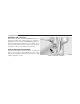
124 UNDERSTANDING THE FEATURES OF YOUR VEHICLE 1. Pull the hood release lever located under the left side of the instrument panel. Safety Latch Use the hood prop rod clipped to the driver’s side of the engine compartment to secure the hood in the open Hood Release Lever 2. Move the safety latch, located under the front edge of position. Place the hood prop at the location stamped into the hood, slightly to the right of center and raise the the inner hood surface. hood.
UNDERSTANDING THE FEATURES OF YOUR VEHICLE 125 CAUTION! To prevent possible damage, do not slam the hood to close it. Lower the hood until it is open approximately 8 in (20 cm) and then drop it. This should secure both latches. Never drive your vehicle unless the hood is fully closed, with both latches engaged. the button. Press the button a second time to turn the light off. The lights also come on when a door is opened or the dimmer control is turned fully upward, past the second detent.
126 UNDERSTANDING THE FEATURES OF YOUR VEHICLE NOTE: The lights will remain on until the switch is pressed a second time, so be sure they have been turned off before leaving the vehicle. These lights will automatically shut off 10 minutes after the ignition is OFF. Further use of the lights, without starting the vehicle, will provide 90 seconds of activity prior to automatic shut off.
UNDERSTANDING THE FEATURES OF YOUR VEHICLE 127 To change the brightness of the instrument panel lights, Daytime Running Lights (DRL) — If Equipped rotate the center portion of the multifunction lever up or The high beam lights will come on as DRL with a lower intensity whenever the ignition is on, the engine is down. running, the headlight switch is off, the parking brake is off, the turn signal is off, and the shift lever is in any position except PARK.
128 UNDERSTANDING THE FEATURES OF YOUR VEHICLE Fog Lights — If Equipped The front fog light switch is on the multifunction lever. To activate the front fog lights, turn on the parking lights or the low beam headlights and pull out the end of the control lever. Fog Lamp Control NOTE: The fog lights will only operate with the headlights on low beam. Selecting high beam headlights will turn off the fog lights.
UNDERSTANDING THE FEATURES OF YOUR VEHICLE 129 High Beam/Low Beam Select Switch Push the multifunction lever away from the steering wheel to switch the headlights to high beam. Pull the lever toward the steering wheel to switch the headlights back to low beam. 3 Turn Signal Control If either light remains on and does not flash, or there is a very fast flash rate, check for a defective outside light bulb.
130 UNDERSTANDING THE FEATURES OF YOUR VEHICLE Flash-to-Pass You can signal another vehicle with your headlights by lightly pulling the multifunction lever toward the steering wheel. This will turn on the high beam headlights until the lever is released. NOTE: If the multifunction lever is held in the flash-topass position for more than 15 seconds, the high beams will shut off. If this occurs, wait 30 seconds for the next flash-to-pass operation.
UNDERSTANDING THE FEATURES OF YOUR VEHICLE 131 Intermittent Wiper System The intermittent feature of this system was designed for use when weather conditions make a single wiping cycle, with a variable pause between cycles, desirable. For maximum delay between cycles, rotate the control knob into the upper end of the delay range. NOTE: If the front wiper is operating when the ignition is turned to LOCK, the wiper will automatically return to the “Park” position.
132 UNDERSTANDING THE FEATURES OF YOUR VEHICLE Windshield Washers To use the washer, pull the control lever toward you and hold while spray is desired. If the lever is pulled while in the delay range, the wiper will operate in low-speed for two wipe cycles after the lever is released, and then resume the intermittent interval previously selected. Push down on the lever to unlock the steering column. With one hand firmly on the steering wheel, move the steering column up or down, as desired.
UNDERSTANDING THE FEATURES OF YOUR VEHICLE 133 WARNING! Tilting the steering column while the vehicle is moving is dangerous. Without a stable steering column, you could lose control of the vehicle and have an accident. Adjust the column only while the vehicle is stopped. Be sure it is locked before driving.
134 UNDERSTANDING THE FEATURES OF YOUR VEHICLE To Activate Push the ON/OFF button. The CRUISE indicator in the instrument cluster will illuminate. To turn the system off, push the ON/OFF button a second time. The CRUISE indicator will turn off. The system should be turned off when not in use. WARNING! Leaving the Electronic Speed Control system on when not in use is dangerous. You could accidentally set the system or cause it to go faster than you want. You could lose control and have an accident.
UNDERSTANDING THE FEATURES OF YOUR VEHICLE 135 To Vary the Speed Setting When the Electronic Speed Control is ON, speed can be increased by pulling up and holding RESUME ACCEL. Release the lever when the desired speed is reached, and the new speed will be set. Manual Transaxle Depressing the clutch pedal will disengage the Electronic Speed Control. A slight increase in engine RPM before the Electronic Speed Control disengages is normal.
136 UNDERSTANDING THE FEATURES OF YOUR VEHICLE door openers, motorized gates, lighting, or home security To Accelerate for Passing Depress the accelerator as you would normally. When the systems. The HomeLink威 unit operates off your vehicle’s pedal is released, the vehicle will return to the set speed. battery. The HomeLink威 buttons that are located in the headliner or sun visor designate the three different HomeLink威 NOTE: The Electronic Speed Control system maintains channels. speed up and down hills.
UNDERSTANDING THE FEATURES OF YOUR VEHICLE 137 NOTE: HomeLink威 is disabled when the Vehicle Security Alarm is active. WARNING! • Your motorized door or gate will open and close while you are training the universal transceiver. Do not train the transceiver if people or pets are in the path of the door or gate. Only use this transceiver with a garage door opener that has a “stop and reverse” feature as required by Federal safety standards.
138 UNDERSTANDING THE FEATURES OF YOUR VEHICLE Your vehicle should be parked outside of the garage Watch for the HomeLink威 indicator to change flash rates. When it changes, it is programmed. It may take up to when programming. 30 seconds, or longer in rare cases. The garage door may Begin Programming open and close while you train. 1. Turn the ignition switch to the ON/RUN position. NOTE: 2.
UNDERSTANDING THE FEATURES OF YOUR VEHICLE 139 If the indicator light stays on constantly, programming is complete and the garage door (or device) should activate when the HomeLink威 button is pressed. If the indicator light blinks rapidly for two seconds and then turns to a constant light, proceed to Step 5 “Programming A Rolling Code System.” 3 5. Programming A Rolling Code System At the garage door opener motor (in the garage), locate the “Learn” or “Training” button.
140 UNDERSTANDING THE FEATURES OF YOUR VEHICLE 6. Firmly press and release the “Learn” or “Training” Using HomeLink威 button. The name and color of the button may vary by To operate, simply press and release the programmed HomeLink威 button. Activation will now occur for the manufacturer. trained device (i.e., garage door opener, gate operator, NOTE: There are 30 seconds in which to initiate the next security system, entry door lock, home/office lighting, step after the “Learn” button has been pressed. etc.
UNDERSTANDING THE FEATURES OF YOUR VEHICLE 141 Gate Operator/Canadian Programming Canadian radio frequency laws require transmitter signals to time-out (or quit) after several seconds of transmission – which may not be long enough for HomeLink威 to pick up the signal during programming. Similar to this Canadian law, some U.S. gate operators are designed to time-out in the same manner. has successfully accepted the frequency signal. The indicator light will flash slowly and then rapidly when fully trained.
142 UNDERSTANDING THE FEATURES OF YOUR VEHICLE Troubleshooting Tips General Information If you are having trouble programming HomeLink威, here This device complies with FCC rules Part 15 and Industry are some of the most common solutions: Canada RSS-210. Operation is subject to the following two conditions: • Replace the battery in the original transmitter. 1. This device may not cause harmful interference. • Press the “Learn” button on the Garage Door Opener to complete the training for a Rolling Code. 2.
UNDERSTANDING THE FEATURES OF YOUR VEHICLE 143 closed and full open. Momentarily pressing the switch POWER SUNROOF — IF EQUIPPED The power sunroof switch is located in the reading lamp. rearward will activate the Express-Open feature, causing the sunroof to open automatically. Press and hold the button in the center of the sunroof switch to open the vent. The sunroof can be stopped at any position between closed and full vent. To close the sunroof from the vent position, press and hold the switch forward.
144 UNDERSTANDING THE FEATURES OF YOUR VEHICLE To close the sunroof, hold the switch in the forward position. Again, any release of the switch will stop the movement and the sunroof will remain in a partial open condition until the switch is pushed forward again. The sunshade can be opened manually. It will also open as the sunroof opens. The sunshade cannot be closed if the sunroof is open. WARNING! • Never leave children in a vehicle with the key in the ignition switch.
UNDERSTANDING THE FEATURES OF YOUR VEHICLE 145 together to minimize the buffeting. If the buffeting occurs with the sunroof open, adjust the sunroof opening to minimize the buffeting or open any window. Sunroof Maintenance Use only a non-abrasive cleaner and a soft cloth to clean the glass panel. ELECTRICAL POWER OUTLETS The 12-Volt power outlets include tethered caps, labeled with a key symbol or battery symbol, indicating power source. All outlets are protected by a single 20 Amp fuse.
146 UNDERSTANDING THE FEATURES OF YOUR VEHICLE There is one optional power outlet located in the right The rear power outlet is powered directly by the battery. rear cargo area. As an option, fuse #11 in the Integrated Power Module (IPM), may be repositioned to allow power to come from the ignition switch only, when in the ON or ACC position. NOTE: The rear power outlet will not accept a cigar lighter unit as it is intended only for accessory items.
UNDERSTANDING THE FEATURES OF YOUR VEHICLE 147 CAUTION! • Many accessories that can be plugged in draw power from the vehicle’s battery, even when not in use (i.e., cellular phones, etc.). Eventually, if plugged in long enough, the vehicle’s battery will discharge sufficiently to degrade battery life and/or prevent the engine from starting. • Accessories that draw higher power (i.e., coolers, vacuum cleaners, lights, etc.), will discharge the battery even more quickly.
148 UNDERSTANDING THE FEATURES OF YOUR VEHICLE and other miscellaneous items. Push the lower button on the front of the armrest, and raise the armrest for access to the lower storage bin. The lower storage area can be used for storing up to six compact discs (CDs) and other miscellaneous items. Sliding Armrest Storage Bins Storage Pockets There are storage pockets located on each door trim panel.
UNDERSTANDING THE FEATURES OF YOUR VEHICLE 149 CAUTION! • Many accessories that can be plugged in draw power from the vehicle’s battery, even when not in use (i.e., cellular phones, etc.). Eventually, if plugged in long enough, the vehicle’s battery will discharge sufficiently to degrade battery life and/or prevent engine starting. • Accessories that draw higher power (i.e., coolers, vacuum cleaners, lights, etc.), will discharge the battery even more quickly.
150 UNDERSTANDING THE FEATURES OF YOUR VEHICLE Position 1 (Top) Insert the front outboard corners of the shelf panel into the top guides and slide forward. Press down on the back of the shelf panel to lock it into place. WARNING! Do not load objects on the shelf in position 1 (top). In an accident, objects could strike occupants causing serious or fatal injury. Position 2 (Middle) Insert the front outboard corners of the shelf panel into the middle guides and slide forward.
UNDERSTANDING THE FEATURES OF YOUR VEHICLE 151 WARNING! Do not load objects over 100 lbs (45 kg) in position 2 (middle). Failure to follow this warning could cause the shelf to collapse resulting in personal injury. Position 3 (Floor) Insert the front outboard corners of the shelf panel into the bottom guides and slide forward. Rear Shelf Panel Position 2 NOTE: To carry items that may soil the carpeting, the rear shelf panel may be inverted in position 2 or position 3.
152 UNDERSTANDING THE FEATURES OF YOUR VEHICLE Position 4 (Vertical) Insert the front outboard corners of the shelf panel into the vertical guides behind the rear seatbacks near the floor and slide downward. Push the shelf panel forward to lock it by aligning the vertical guide with the rubber stop of the shelf panel. WARNING! When in the vertical position, the rear shelf panel should not be used as a barrier for large objects in the cargo area with the seatbacks folded down.
UNDERSTANDING THE FEATURES OF YOUR VEHICLE 153 2. Twist the knob on the underside of the panel and lower the shelf leg. 3 Rear Shelf Panel Position 5 Rear Shelf Leg Release Knob 3. Install the shelf leg into the liftgate latch area as labeled on the rear scuff plate. WARNING! Do not load objects over 100 lbs (45 kg) in position 5 (table). Failure to follow this warning could cause the shelf to collapse resulting in personal injury.
154 UNDERSTANDING THE FEATURES OF YOUR VEHICLE REAR WINDOW FEATURES Rear Window Defroster The rear window defroster button is located on the center of the instrument panel, below the radio. Press this button to turn on the rear window defroster and the heated outside mirrors (if equipped). An indicator in the button will illuminate when the rear window defroster is on. The rear window defroster automatically turns off after approximately 10 minutes.
UNDERSTANDING THE FEATURES OF YOUR VEHICLE 155 Rear Wiper/Washer Switch — If Equipped A switch on the right side of the steering column controls operation of the Rear Wiper/Washer function. Rotating the center of the switch forward to the on position will activate the wiper. Rotating the center of the switch all the way forward will turn on the wash function. The washer pump will continue to operate as long as the button is pressed.
UNDERSTANDING YOUR INSTRUMENT PANEL CONTENTS 䡵 Instrument Panel Features . . . . . . . . . . . . . . . 160 ▫ Compass/Temperature Display . . . . . . . . . . 175 䡵 Instrument Cluster — Base . . . . . . . . . . . . . . . 161 ▫ Odometer Display . . . . . . . . . . . . . . . . . . . . 177 䡵 Instrument Cluster — Premium . . . . . . . . . . . 162 ▫ Trip Odometer (ODO) . . . . . . . . . . . . . . . . . 177 䡵 Instrument Cluster — Turbo . . . . . . . . . . . . . .
158 UNDERSTANDING YOUR INSTRUMENT PANEL 䡵 Sales Code RAQ – AM/FM/CD (6-Disc) Radio With Optional uconnect威 studios (Satellite Radio), uconnect威 phone, And Video Entertainment Systems (VES)™ Capabilities . . . 187 䡵 Sales Code REF — AM/FM/CD (Single-Disc) Radio With Optional uconnect威 studios (Satellite Radio) And uconnect威 phone Capability . . . . . . . . . . . . . . . . . . . . . . . . . . . 201 ▫ Operating Instructions - Radio Mode . . . . . . 188 ▫ Operating Instructions - Radio Mode . . . . . .
UNDERSTANDING YOUR INSTRUMENT PANEL 159 ▫ Electronic Serial Number/Sirius Identification Number (ESN/SID) . . . . . . . . . 209 ▫ Selecting uconnect威 studios (Satellite) Mode In REF, And RAQ, Radios . . . . . . . . . . . . . . 210 ▫ Selecting a Channel . . . . . . . . . . . . . . . . . . . 210 ▫ Storing And Selecting Pre-Set Channels . . . . . 211 ▫ Using The PTY (Program Type) Button (If Equipped) . . . . . . . . . . . . . . . . . . . . . . . 211 ▫ PTY Button ⬙Scan⬙ . . . . . . . . . . . . . . . . . . . .
160 UNDERSTANDING YOUR INSTRUMENT PANEL INSTRUMENT PANEL FEATURES 1 — Air Vent 2 — Instrument Cluster 3 — Power Windows 4 — Analog Clock * If Equipped 5 6 7 8 — Radio — Assist Handle — Glove Compartment — Heated Seats * 9 — TRAC Off 10 — Climate Controls 11 — Storage Cubby 12 — Pass Air Bag Off — If Equipped 13 — Hazard Lights 14 — Rear Window Defrost * 15 — Side Mirror Control *
UNDERSTANDING YOUR INSTRUMENT PANEL 161 INSTRUMENT CLUSTER — BASE 4
162 UNDERSTANDING YOUR INSTRUMENT PANEL INSTRUMENT CLUSTER — PREMIUM
UNDERSTANDING YOUR INSTRUMENT PANEL 163 INSTRUMENT CLUSTER — TURBO 4
164 UNDERSTANDING YOUR INSTRUMENT PANEL INSTRUMENT CLUSTER DESCRIPTIONS 1. Fuel Gauge When the ignition switch is in the ON position, the pointer will show the level of fuel remaining in the fuel tank. 2. Fuel Door Reminder This is a reminder that the Fuel Filler Door is located on the front passenger’s (right) side of the vehicle. 3. Temperature Gauge The temperature gauge shows engine coolant temperature.
UNDERSTANDING YOUR INSTRUMENT PANEL 165 WARNING! A hot engine cooling system is dangerous. You or others could be badly burned by steam or boiling coolant. You may want to call an authorized dealership for service if your vehicle overheats. If you decide to look under the hood yourself, see Section 7 of this manual. Follow the warnings under the Cooling System Pressure Cap paragraph. 4. Speedometer The Speedometer shows the vehicle speed in miles per hour (mph) and/or kilometers per hour (km/h). 5.
166 UNDERSTANDING YOUR INSTRUMENT PANEL As an added safety feature, your vehicle has been equipped with a Tire Pressure Monitoring System (TPMS) that illuminates a low tire pressure telltale when one or more of your tires is significantly under-inflated. Accordingly, when the low tire pressure telltale illuminates, you should stop and check your tires as soon as possible, and inflate them to the proper pressure.
UNDERSTANDING YOUR INSTRUMENT PANEL 167 CAUTION! The TPMS has been optimized for the original equipment tires and wheels. TPMS pressures and warning have been established for the tire size equipped on your vehicle. Undesirable system operation or sensor damage may result when using replacement equipment that is not of the same size, type, and/or style. Aftermarket wheels can cause sensor damage.
168 UNDERSTANDING YOUR INSTRUMENT PANEL GASCAP If the vehicle diagnostic system detects a leak or change in the evaporative system, or the fuel filler cap is loose, improperly installed, or damaged, the words “GASCAP” will display in the odometer. If this occurs, tighten the fuel filler cap properly and press the odometer reset button to turn off the “GASCAP” message. (Refer to “Onboard Diagnostic System — OBDII” in Section 7 of this manual for more information).
UNDERSTANDING YOUR INSTRUMENT PANEL 169 13. Turn Signal Indicators 11. Odometer/Trip Odometer Reset Button The arrow will flash with the exterior turn signal Press this button to change the display from odometer to when the turn signal lever is operated. either of the two trip odometer settings. Trip A or Trip B will appear when in the trip odometer mode. Push in and 14.
170 UNDERSTANDING YOUR INSTRUMENT PANEL If the light remains on when the parking brake has been disengaged, and the fluid level is at the full mark on the master cylinder reservoir, it indicates a possible brake hydraulic system malfunction or that a problem with the Brake Booster has been detected by the Anti-Lock Brake System (ABS) / Electronic Stability Program (ESP) system. In this case, the light will remain on until the condition has been corrected.
UNDERSTANDING YOUR INSTRUMENT PANEL 171 Operation of the Brake Warning Light can be checked by turning the ignition switch from the OFF position to the ON position. The light should illuminate for approximately two seconds. The light should then turn off unless the parking brake is applied or a brake fault is detected. If the light does not illuminate, have the light inspected by an authorized dealer. unbuckled, the Seat Belt Reminder Light will illuminate and the chime will sound.
172 UNDERSTANDING YOUR INSTRUMENT PANEL normal, turn the engine off immediately and call for 21. Anti-Lock Brake (ABS) Light service. Refer to “If Your Engine Overheats” in Section 6 This light monitors the Anti-Lock Brake System (ABS). The light will turn on when the ignition for more information. switch is turned to the ON position and may 18. Low Fuel Light stay on for as long as four seconds. When the fuel level reaches approximately 2.0 gal (7.
UNDERSTANDING YOUR INSTRUMENT PANEL 173 22. Oil Pressure Warning Light This light indicates low engine oil pressure. The light should turn on momentarily when the engine is started. If the light turns on while driving, stop the vehicle and shut off the engine as soon as possible. A chime will sound for four minutes when this light turns on. 24. High Beam Indicator This indicator shows that the high beam headlights are on.
174 UNDERSTANDING YOUR INSTRUMENT PANEL exist, this display shows the EVIC messages. Refer to Compass Mini-Trip Computer Reset Button “Electronic Vehicle Information Center” in this section. CMTC Reset Button — Secondary Reset Button On vehicles equipped with Compass Mini-Trip Com- Press the left Compass/Temperature RESET button to puter (CMTC) the display provides the outside tempera- scroll through sub-menus (i.e.
UNDERSTANDING YOUR INSTRUMENT PANEL 175 Compass/Temperature Display Compass Variance Compass Variance is the difference between Magnetic North and Geographic North. To ensure compass accuracy, the compass variance should be properly set according to the variance map for the zone where the vehicle will be driven. When properly set, the compass will automatically account for this difference.
176 UNDERSTANDING YOUR INSTRUMENT PANEL the zone, press and release the RESET button to incre- Calibrate the compass by driving slowly, under 5 mph ment the variance one step. Repeat as necessary, until the (8 km/h) in one or more complete circles in a area free from large metallic objects, until the CAL indicator in the desired variance is achieved. CMTC turns off. The compass will now function NOTE: Zone 8 is the factory default. During programnormally.
UNDERSTANDING YOUR INSTRUMENT PANEL 177 3. Release the RESET button, then press and hold again (approximately 10 seconds), until the direction is displayed with the CAL indicator on continuously in the display. Trip Odometer (ODO) This display shows the distance traveled since the last reset. Press and release the right button (on the instrument cluster) to switch from odometer, to trip A or trip B. Press and hold the right button while the odometer/trip 4.
178 UNDERSTANDING YOUR INSTRUMENT PANEL ELECTRONIC VEHICLE INFORMATION CENTER (EVIC) – IF EQUIPPED EVIC Operation The Electronic Vehicle Information Center (EVIC) features a driver-interactive display that is located in the instrument cluster.
UNDERSTANDING YOUR INSTRUMENT PANEL 179 When the appropriate conditions exist, the EVIC displays • Left/Right Rear Door Ajar (one or more, with a single the following messages: chime, if speed is above 1 mph) • Turn Signal On (with a continuous warning chime) • Left Front Turn Signal Lamp Out (with a single chime) • Left Rear Turn Signal Lamp Out (with a single chime) • Door(s) Ajar (with a single chime, if vehicle is in motion) • Trunk Ajar (with a single chime) • Headlights On • Right Front Turn Signal
180 UNDERSTANDING YOUR INSTRUMENT PANEL • Tire Pressure Monitor (TPM) • Personal Settings displayed. To reset all resettable functions, press and release the EVIC button a second time within three seconds of resetting the currently-displayed function (Reset ALL will be displayed during this three-second window).
UNDERSTANDING YOUR INSTRUMENT PANEL 181 history information will be erased, and the averaging will FUEL text and a new DTE value will be displayed, based on the current values in the DTE calculation and the continue from where it was before the reset. current fuel tank level. Distance To Empty (DTE) Shows the estimated distance that can be travelled with Elapsed Time the fuel remaining in the tank.
182 UNDERSTANDING YOUR INSTRUMENT PANEL Press and release the EVIC button until “Personal Set- Lock Doors Automatically at 15 MPH (24 Km/h) When ON is selected, all doors lock automatically when tings” is displayed in the EVIC. the speed of the vehicle reaches 15 mph (24 km/h). Press Use the EVIC button to display one of the following and hold the EVIC button when in this display until ON choices: or OFF appears, to make your selection.
UNDERSTANDING YOUR INSTRUMENT PANEL 183 Remote Unlock All Doors is selected, all doors will unlock at the first press of the RKE transmitter UNLOCK button. Press and hold the EVIC button when in this display until Driver’s Door 1st or All Doors appears, to make your selection. without the Sound Horn On Lock feature activated. Press and hold the EVIC button when in this display until ON or OFF appears, to make your selection.
184 UNDERSTANDING YOUR INSTRUMENT PANEL Turn Headlights on with Remote Key Unlock When this feature is selected, the headlights will activate and remain on for up to 90 seconds when the doors are unlocked using the RKE transmitter. Press and hold the EVIC button when in this display until OFF, 30 sec, 60 sec, or 90 sec appears, to make your selection. Automatic Compass Calibration The compass on your vehicle is self-calibrating, eliminating the need to manually calibrate the compass.
UNDERSTANDING YOUR INSTRUMENT PANEL 185 • Keep all magnetic objects, such as laptop computers, iPod’s, cell phones and PDA’s (anything with a battery) away from the compass sensor which is located in the top of the instrument panel. These devices can interfere with compass accuracy and performance. Manual Compass Calibration If the compass appears to be inaccurate, you may wish to manually calibrate the compass. Prior to calibrating the compass, make sure the proper Compass Variance Value is selected.
186 UNDERSTANDING YOUR INSTRUMENT PANEL differences, the variance should be set for the zone where the vehicle is driven, per the zone map. Once properly set, the compass will automatically compensate for the differences and provide the most accurate compass heading. To Set the Variance Follow this procedure to set the Variance: 1. Turn the ignition switch to the ON position. Leave the shift lever in PARK. 2.
UNDERSTANDING YOUR INSTRUMENT PANEL 187 5. Press and release the EVIC button to exit. SALES CODE RAQ – AM/FM/CD (6-DISC) RADIO WITH OPTIONAL uconnect姞 studios (SATELLITE SETTING THE ANALOG CLOCK RADIO), uconnect姞 phone, AND VIDEO To set the analog clock at the top center of the instrument ENTERTAINMENT SYSTEMS (VES)™ panel, press and hold the button until the setting is CAPABILITIES correct.
188 UNDERSTANDING YOUR INSTRUMENT PANEL MODE Button (Radio Mode) Press the MODE button repeatedly to select between the NOTE: The ignition switch must be in the ON or ACC CD player, Satellite Radio, or Video Entertainment Sysposition to operate the radio. tem (VES)™ (if equipped). Power Switch/Volume Control (Rotary) SEEK Button (Radio Mode) Push the ON/VOL control to turn the radio ON. Push the Press and release the SEEK button to search for the next ON/VOL a second time to turn OFF the radio.
UNDERSTANDING YOUR INSTRUMENT PANEL 189 will return. Rotating the volume control, turning the TIME Button radio ON/OFF, or turning OFF the ignition will also Press the TIME button and the time of day will be displayed for 5 seconds. return the sound from the speakers NOTE: In Hands Free Phone (if equipped) mode, the Clock Setting Procedure MUTE button mutes the microphone. 1. Press and hold the TIME button until the hours blink. SCAN Button (Radio Mode) 2.
190 UNDERSTANDING YOUR INSTRUMENT PANEL RW/FF (Radio Mode) Pressing the Rewind/Fast Forward button causes the tuner to search for the next frequency in the direction of the arrows. This feature operates in either AM, FM or Satellite (if equipped) frequencies. Press the rotary TUNE control a second time and “MID” will display. Turn the TUNE control to the right or left to increase or decrease the Mid Range tones. Press the rotary TUNE control a third time and “TREBLE” will display.
UNDERSTANDING YOUR INSTRUMENT PANEL 191 RND/PTY Button (Program Type Radio Mode) Pressing this button once will turn on the PTY mode for 5 seconds. If no action is taken during the 5 second time out the PTY icon will turn off. Pressing the PTY button or turning the TUNE rotary knob within 5 seconds will allow the program format type to be selected. Many radio stations do not currently broadcast PTY information.
192 UNDERSTANDING YOUR INSTRUMENT PANEL SET/DIR Button (Radio Mode) — To Set the Pushbutton Memory When you are receiving a station that you wish to Soft Rock commit to pushbutton memory, press the SET/DIR butSoft Rhythm and Blues ton. The symbol SET 1 will now show in the display Sports window. Select the button (1-6) you wish to lock onto this Talk station and press and release that button.
UNDERSTANDING YOUR INSTRUMENT PANEL 193 Every time a preset button is used a corresponding Inserting Compact Disc(s) Gently insert one CD into the CD player with the CD button number will be displayed. label facing up. The CD will automatically be pulled into Buttons 1 - 6 (Radio Mode) the CD player and the CD icon will illuminate on the These buttons tune the radio to the stations that you radio display. commit to pushbutton memory {12 AM, 12 FM, and 12 Satellite (if equipped) stations}.
194 UNDERSTANDING YOUR INSTRUMENT PANEL SEEK Button (CD Mode for CD Audio Play) LOAD/EJECT Button (CD Mode for CD Audio Press the right side of the SEEK button for the next Play) selection on the CD. Press the left side of the button to LOAD/ EJECT - Load return to the beginning of the current selection, or return Press the LOAD/ EJECT button and the pushto the beginning of the previous selection if the CD is button with the corresponding number where within the first 10 seconds of the current selection.
UNDERSTANDING YOUR INSTRUMENT PANEL 195 radio display will show ⬙EJECTING DISC⬙ when the disc TIME Button (CD Mode for CD Audio Play) is being ejected and prompt the user to remove the disc. Press this button to change the display from a large CD playing time display to a small CD playing time display. Press and hold the LOAD/ EJECT button for 5 seconds RW/FF (CD Mode for CD Audio Play) and all CDs will be ejected from the radio.
196 UNDERSTANDING YOUR INSTRUMENT PANEL RND/PTY Button (Random Play Button) (CD Mode for CD Audio Play) Press this button while the CD is playing to activate Random Play. This feature plays the selections on the compact disc in random order to provide an interesting change of pace. Notes On Playing MP3 Files The radio can play MP3 files, however, acceptable MP3 file recording media and formats are limited. When writing MP3 files, pay attention to the following restrictions.
UNDERSTANDING YOUR INSTRUMENT PANEL 197 The radio uses the following limits for file systems: • Maximum number of directory levels: 15 • Maximum number of files: 255 • Maximum number of folders: 100 • Maximum number of characters in file/folder names: Supported MP3 File Formats The radio will recognize only files with the *.mp3 extension as MP3 files. Non-MP3 files named with the *.mp3 extension may cause playback problems.
198 UNDERSTANDING YOUR INSTRUMENT PANEL MPEG Specification MPEG-1 Audio Layer 3 MPEG-2 Audio Layer 3 Sampling Frequency (kHz) 48, 44.1, 32 24, 22.05, 16 Bit rate (kbps) 320, 256, 224, 192, 160, 128, 112, 96, 80, 64, 56, 48, 40, 32 160, 128, 144, 112, 96, 80, 64, 56, 48, 40, 32, 24, 16, 8 Playback of MP3 Files When a medium containing MP3 data is loaded, the radio checks all files on the medium.
UNDERSTANDING YOUR INSTRUMENT PANEL 199 LOAD/ EJECT - Eject Press the LOAD/ EJECT button and the pushbutton with the corresponding number where SEEK Button (CD Mode for MP3 Play) the CD was loaded and the disc will unload Pressing the right side of the SEEK button plays the next and move to the entrance for easy removal. The MP3 File. Pressing the left side of the SEEK button plays radio display will show ⬙EJECTING DISC⬙ when the disc the beginning of the MP3 file.
200 UNDERSTANDING YOUR INSTRUMENT PANEL MSG or INFO Button (CD Mode for MP3 Play) Press and MSG or INFO button while playing MP3 disc. The radio scrolls through the following TAG information: Song Title, Artist, File Name, and Folder Name (if available). AM/FM Button (CD Mode for MP3 Play) Switches back to radio mode. RND/ PTY Button (CD Mode for MP3 Play) Pressing this button plays files randomly.
UNDERSTANDING YOUR INSTRUMENT PANEL 201 Operating Instructions - uconnect威 studios (Satellite Radio) (If Equipped) Refer to the uconnect威 studios (Satellite Radio) section of the Owner’s Manual. Operating Instructions - Video Entertainment System (VES)™ (If Equipped) Refer to separate Video Entertainment System (VES)™ Guide.
202 UNDERSTANDING YOUR INSTRUMENT PANEL Power Switch/Volume Control (Rotary) SEEK Button (Radio Mode) Push the ON/VOL control to turn the radio ON. Push the Press and release the SEEK button to search for the next ON/VOL a second time to turn OFF the radio. listenable station in either AM/FM or Satellite (if equipped) mode. Press the right side of the button to seek Electronic Volume Control up and the left side to seek down.
UNDERSTANDING YOUR INSTRUMENT PANEL 203 SCAN Button (Radio Mode) Pressing the SCAN button causes the tuner to search for the next listenable station in either, AM, FM, or Satellite (if equipped) frequencies, pausing for five seconds at each listenable station before continuing to the next. To stop the search, press SCAN a second time.
204 UNDERSTANDING YOUR INSTRUMENT PANEL AM/FM Button (Radio Mode) Press the button to select AM or FM modes. Press the rotary TUNE control a fifth time and “FADE” will display. Turn the TUNE control to the left or right to adjust the sound level between the front and rear speakers. Setting the Tone, Balance, and Fade Press the rotary TUNE control, and “BASS” will display.
UNDERSTANDING YOUR INSTRUMENT PANEL 205 the SET button twice and “SET 2” will show in the display window. Each button can be set for SET 1 and SET 2 in both AM and FM. This allows a total of 12 AM, 12 FM, and 12 Satellite (if equipped) stations to be stored into pushbutton memory. The stations stored in SET 2 memory can be selected by pressing the pushbutton twice. Inserting The Compact Disc (Single CD Player) Gently insert one CD into the CD player with the CD label facing up.
206 UNDERSTANDING YOUR INSTRUMENT PANEL SEEK Button (CD Mode) EJECT Button (CD Mode) Press the right side of the SEEK button for the next track Press this button and the disc will unload and on the CD. Press the left side of the button to return to the move to the entrance for easy removal. The beginning of the current track, or return to the beginning unit will switch to the last selected mode. of the previous track if the CD is within the first 10 seconds of the current selection.
UNDERSTANDING YOUR INSTRUMENT PANEL 207 Press and hold the FF button to fast forward through the MP3 player, cassette player, or microphone and utilize tracks. Release the FF button to stop the fast forward the vehicle’s audio system to amplify the source and play feature. If the RW button is pressed, the current track will through the vehicle speakers. reverse to the beginning of the track and begin playing.
208 UNDERSTANDING YOUR INSTRUMENT PANEL second time and the sound from the speakers will return. RW/FF (Auxiliary Mode) Rotating the volume control or turning the ignition No function. OFF/ON will also return the sound from the speakers. RND/SET Button (Auxiliary Mode) SCAN Button (Auxiliary Mode) No function. No function. MODE Button (Auxiliary Mode) EJECT Button (Auxiliary Mode) Press the MODE button repeatedly to select between the CD player and Satellite Radio (if equipped). No function.
UNDERSTANDING YOUR INSTRUMENT PANEL 209 uconnect姞 studios (SATELLITE RADIO) — IF EQUIPPED Satellite radio uses direct satellite to receiver broadcasting technology to provide clear digital sound, coast to coast. The subscription service provider is Sirius Satellite Radio. This service offers over 100 channels of music, sports, news, entertainment, and programming for children, directly from its satellites and broadcasting studios.
210 UNDERSTANDING YOUR INSTRUMENT PANEL ESN/SID Access With RAQ Radios With the ignition switch in the ACCESSORY position and the radio OFF, press the CD Eject and TIME buttons simultaneously for 3 seconds. All twelve ESN/SID numbers will be displayed. The radio will exit the ESN/SID mode when any other button is pushed, the ignition is turned OFF, or 5 minutes has passed since any button was pushed. ESN/SID Access With Navigation Radios Please refer to your Navigation User’s Manual.
UNDERSTANDING YOUR INSTRUMENT PANEL 211 moving on to the next channel. The word ⬙SCAN⬙ will PTY Button ⴖSCANⴖ appear in the display between each channel change. Press When the desired program type is obtained, press the ⬙SCAN⬙ button within five seconds. The radio will play the SCAN button a second time to stop the search. 7 seconds of the selected channel before moving to the NOTE: Channels that may contain objectionable content next channel of the selected program type. Press the can be blocked.
212 UNDERSTANDING YOUR INSTRUMENT PANEL placed within the line of sight of the antenna will cause decreased performance. Larger luggage items should be placed as far forward as possible. Do not place items directly on or above the antenna. The luggage rack (if equipped), should also not be positioned directly above the antenna. CD/DVD MAINTENANCE To keep a CD/DVD in good condition, take the following precautions: 1. Handle the disc by its edge; avoid touching the surface. 2.
UNDERSTANDING YOUR INSTRUMENT PANEL 213 NOTE: If you experience difficulty in playing a particular disc, it may be damaged (i.e., scratched, reflective coating removed, a hair, moisture or dew on the disc) oversized, or have protection encoding. Try a known good disc before considering disc player service. RADIO OPERATION AND CELLULAR PHONES Under certain conditions, the cellular phone being on in your vehicle can cause erratic or noisy performance from your radio.
214 UNDERSTANDING YOUR INSTRUMENT PANEL NOTE: The air conditioning system of your vehicle Mode Control (Air Direction) The Mode control allows you to contains R-134a, a refrigerant that does not deplete the choose from several patterns of air ozone layer in the upper atmosphere. distribution. You can select either The controls are as follows: a primary mode, as identified by Fan Control the symbols, or a blend of two of Use the Fan control to regulate the these modes.
UNDERSTANDING YOUR INSTRUMENT PANEL 215 NOTE: There is a difference in temperature between the Defrost upper and lower outlets for added comfort. The warmer Air is directed through the windshield and side window demist outlets. Use this mode with maxiair goes to the floor outlets. This feature gives improved mum fan and temperature settings for best windshield comfort during sunny but cool conditions. and side window defrosting.
216 UNDERSTANDING YOUR INSTRUMENT PANEL CAUTION! If the Defroster is not working the windshield and windows may become fogged, and your visibility will be greatly diminished. See your authorized dealer as soon as possible. Temperature Control Use this control to regulate the temperature of the air inside the passenger compartment. The blue area of the scale indicates cooler temperatures while the red area indicates warmer temperatures.
UNDERSTANDING YOUR INSTRUMENT PANEL 217 Air Conditioning (A/C) — If Equipped MAX A/C Press the A/C button to engage the air conditioning. A lamp will illuminate when the air conditioning system is engaged To quickly cool the vehicle interior follow the steps listed below: 4 NOTE: The air conditioning compressor will not engage 1. Set the Temperature Control to Max Cool. until the engine has been running for about 10 seconds. 2. Set the Mode Control to Panel or Bi-Level. 3.
218 UNDERSTANDING YOUR INSTRUMENT PANEL NOTE: Continuous use of the Recirculation mode may NOTE: • Recirculation Mode will not operate in Floor, Mix or make the inside air stuffy and window fogging may occur. Extended use of this mode is not recommended. Defrost modes. • See “Circulation Control” in this section, for proper or In cold or damp weather, the use of the Recirculation mode will cause windows to fog on the inside because of extended use of this position. moisture buildup inside the vehicle.
UNDERSTANDING YOUR INSTRUMENT PANEL 219 Operating Tips 4 Operating Tips
220 UNDERSTANDING YOUR INSTRUMENT PANEL Window Fogging Vehicle side windows tend to fog on the inside in mild, rainy or humid weather. To clear the windows, use the A/C, Panel and Blower controls. Direct the panel outlets toward the side windows. Do not use recirculate without A/C for long periods, as fogging may occur. raise the boiling point of the coolant for protection against overheating. A 50% concentration is recommended.
STARTING AND OPERATING CONTENTS 䡵 Starting Procedures . . . . . . . . . . . . . . . . . . . . 224 䡵 Manual Transaxle — If Equipped . . . . . . . . . . 226 ▫ Manual Transaxle — If Equipped . . . . . . . . . 224 ▫ Five–Speed Manual Transaxle . . . . . . . . . . . 226 ▫ Automatic Transaxle — If Equipped . . . . . . . 224 䡵 Automatic Transaxle — If Equipped . . . . . . . . 229 ▫ Normal Starting . . . . . . . . . . . . . . . . . . . . . 224 ▫ Brake/Transmission Interlock System . . . . . .
222 STARTING AND OPERATING 䡵 Driving On Slippery Surfaces . . . . . . . . . . . . . 236 䡵 Tire Safety Information . . . . . . . . . . . . . . . . . 248 ▫ Acceleration . . . . . . . . . . . . . . . . . . . . . . . . 236 ▫ Tire Markings . . . . . . . . . . . . . . . . . . . . . . . 248 ▫ Traction . . . . . . . . . . . . . . . . . . . . . . . . . . . 237 ▫ Tire Identification Number (TIN) . . . . . . . . . 251 䡵 Driving Through Water . . . . . . . . . . . . . . . . .
STARTING AND OPERATING 223 䡵 Adding Fuel . . . . . . . . . . . . . . . . . . . . . . . . . 274 䡵 Trailer Towing . . . . . . . . . . . . . . . . . . . . . . . . 278 ▫ Fuel Filler Cap (Gas Cap) . . . . . . . . . . . . . . 274 ▫ Common Towing Definitions . . . . . . . . . . . . 278 ▫ Loose Fuel Filler Cap Message . . . . . . . . . . . 276 ▫ Towing Tips . . . . . . . . . . . . . . . . . . . . . . . . 288 䡵 Vehicle Loading . . . . . . . . . . . . . . . . . . . . . .
224 STARTING AND OPERATING STARTING PROCEDURES Automatic Transaxle — If Equipped Before starting your vehicle, adjust your seat, adjust both The shift lever must be in the NEUTRAL or PARK inside and outside mirrors, and fasten your seat belts. position before you can start the engine. Apply the brakes and press the shift lever knob button before shifting to WARNING! any driving gear. Never leave children alone in a vehicle. Leaving unattended children in a vehicle is dangerous for a number of reasons.
STARTING AND OPERATING 225 WARNING! Do not attempt to push or tow your vehicle to get it started. Vehicles equipped with an automatic transaxle cannot be started this way. Unburned fuel could enter the catalytic converter and once the engine has started, ignite and damage the converter and vehicle. If the vehicle has a discharged battery, booster cables may be used to obtain a start from another vehicle. This type of start can be dangerous if done improperly, so follow the procedure carefully.
226 STARTING AND OPERATING CAUTION! To prevent damage to the starter, do not crank the engine for more than 15 seconds at a time. Wait 10 to 15 seconds before trying again. TURBOCHARGER ⴖCOOL-DOWNⴖ CHART Driving Conditions Idle Before Shutdown Normal 0 min Aggressive/Heavy Load 3 min Trailer Tow 5 min After Starting MANUAL TRANSAXLE — IF EQUIPPED The idle speed will automatically decrease as the engine Five–Speed Manual Transaxle warms up.
STARTING AND OPERATING 227 Fully press the clutch pedal before you shift gears. As you Use each gear in numerical order - do not skip a gear. Be release the clutch pedal, lightly press the accelerator sure the shift lever is in first gear, (not third gear), when pedal. starting from a standing position. Damage to the clutch can result from starting in third gear. For most city driving you will find it easier to use only the lower gears.
228 STARTING AND OPERATING Recommended Shift Speeds To use your manual transaxle for optimal fuel economy, it should be upshifted as listed in Table 1. Table 1 - Manual Transaxle Normal Acceleration and Cruise Shift Speeds in MPH (km/h) Engine Mode Accel2.4L eration NonTurbo Cruise 1 to 2 2 to 3 3 to 4 4 to 5 Table 2 - Manual Transaxle Maximum Performance Shift Speeds in MPH (km/h) Engine 2.
STARTING AND OPERATING 229 Downshifting AUTOMATIC TRANSAXLE — IF EQUIPPED Proper downshifting will improve fuel economy and WARNING! prolong engine life. CAUTION! If you skip a gear while downshifting or downshift at too high of an engine speed, you could damage the engine, transmission, or clutch. To maintain a safe speed and prolong brake life, shift down to second or first gear when descending a steep grade.
230 STARTING AND OPERATING CAUTION! Damage to the transaxle may occur if the following precautions are not observed: • Shift into PARK only after the vehicle has come to a complete stop. • Shift into or out of REVERSE only after the vehicle has come to a complete stop and the engine is at idle speed. • Do not shift from REVERSE, PARK, or NEUTRAL into any forward gear when the engine is above idle speed. • Before shifting into any gear, make sure your foot is firmly on the brake pedal.
STARTING AND OPERATING 231 NOTE: If a malfunction occurs, the system will trap the key in the ignition cylinder to warn you that this safety feature is inoperable. The engine can be started and stopped but the key cannot be removed until you obtain service. RESET Mode The transaxle is monitored electronically for abnormal conditions. If a condition is detected that could cause damage, the transaxle shifts automatically into second gear.
232 STARTING AND OPERATING NOTE: Even if the transaxle can be reset, it is recommended that you visit an authorized dealer at your earliest possible convenience. Your authorized dealer has diagnostic equipment to determine if the problem could recur. Gear Ranges DO NOT race the engine when shifting from PARK or NEUTRAL positions into another gear range. WARNING! Unintended movement of a vehicle could injure those in and near the vehicle.
STARTING AND OPERATING 233 • Look at the shift indicator window on the console to NEUTRAL This range is used when vehicle is standing for proensure it is in the PARK position. longed periods with engine running. Engine may be • When engaged in PARK, you will not be able to move started in this range. Set the parking brake if you must the shift lever rearward without pressing the lever leave the vehicle. knob button.
234 STARTING AND OPERATING When frequent transaxle shifting occurs while using the DRIVE/OVERDRIVE range, such as when operating the vehicle under heavy loading conditions (in hilly terrain, traveling into strong head winds, or while towing trailers), use third gear. LOW — 1st This range should be used for maximum engine braking when descending steep grades. In this range, up shifts will occur only to prevent engine over speed while down shifts from second to first gear will occur as early as possible.
STARTING AND OPERATING 235 Operation The Autostick威 position is just below the OVERDRIVE position and is identified by the word “Autostick”. When you move the shift lever into the Autostick威 position, it can be moved from side to side. Moving the lever to the left (-) triggers a downshift and to the right (+) an upshift. The gear position will be shown in the gear display, located in the instrument cluster.
236 STARTING AND OPERATING • The transaxle will automatically upshift from first to • If the system detects powertrain overheating, the second gear and from second to third gear when transaxle will revert to the automatic shift mode and engine speed reaches about 6,300 RPM. remain in that mode until the powertrain cools off.
STARTING AND OPERATING 237 WARNING! Rapid acceleration on slippery surfaces is dangerous. Unequal traction can cause sudden pulling of the front wheels. You could lose control of the vehicle and possibly have an accident. Accelerate slowly and carefully whenever there is likely to be poor traction (ice, snow, wet, mud, loose sand, etc.). Traction When driving on wet or slushy roads, it is possible for a wedge of water to build up between the tire and road surface.
238 STARTING AND OPERATING Flowing/Rising Water WARNING! Do not drive on or across a road or path where water is flowing and/or rising (as in storm run-off). Flowing water can wear away the road or path’s surface and cause your vehicle to sink into deeper water. Furthermore, flowing and/or rising water can carry your vehicle away swiftly. Failure to follow this warning may result in injuries that are serious or fatal to you, your passengers, and others around you.
STARTING AND OPERATING 239 CAUTION! (Continued) WARNING! • Driving through standing water may cause damage to your vehicle’s drivetrain components. Always inspect your vehicle’s fluids (i.e., engine oil, transmission/transaxle, axle, etc.) for signs of contamination (i.e., fluid that is milky or foamy in appearance) after driving through standing water. Do not continue to operate the vehicle if any fluid appears contaminated, as this may result in further damage.
240 STARTING AND OPERATING POWER STEERING The standard power steering system will give you good vehicle response and increased ease of maneuverability in tight spaces. The system will provide mechanical steering capability if power assist is lost. If for some reason the power assist is interrupted, it will still be possible to steer your vehicle. Under these conditions, you will observe a substantial increase in steering effort, especially at very low vehicle speeds and during parking maneuvers.
STARTING AND OPERATING 241 Power Steering Fluid Check Checking the power steering fluid level at a defined service interval is not required. The fluid should only be checked if a leak is suspected, abnormal noises are apparent, and/or the system is not functioning as anticipated. Coordinate inspection efforts through an authorized dealer. CAUTION! Do not use chemical flushes in your power steering system as the chemicals can damage your power steering components.
242 STARTING AND OPERATING If the parking brake is applied while the vehicle is moving, a chime will sound to alert the driver. The chime will sound up to 10 times, or until the vehicle has returned to a stop. Before leaving the vehicle, make sure that the parking brake is set. To set the parking brake, pull up firmly on the lever. Always move the shift lever into the PARK position (automatic transaxle) or into the REVERSE position (manual transaxle).
STARTING AND OPERATING 243 As an added precaution, turn the front wheels toward the BRAKE SYSTEM curb on a downhill grade and away from the curb on an Your vehicle is equipped with power-assisted brakes as standard equipment. In the event power-assist is lost for uphill grade. any reason (for example, repeated brake applications Always apply the parking brake before leaving the with the engine off), the brakes will still function. Howvehicle.
244 STARTING AND OPERATING If either of the two hydraulic systems lose normal capability, the remaining system will still function with some loss of overall braking effectiveness. This will be evident by increased pedal travel during application and greater pedal force required to slow or stop. In addition, if the malfunction is caused by an internal leak, as the brake fluid in the master cylinder drops, the “Brake Warning Light” will illuminate.
STARTING AND OPERATING 245 WARNING! (Continued) • The ABS cannot prevent accidents, including those resulting from excessive speed in turns, following another vehicle too closely, or hydroplaning. Only a safe, attentive, and skillful driver can prevent accidents. • The capabilities of an ABS-equipped vehicle must never be exploited in a reckless or dangerous manner that could jeopardize the user’s safety or the safety of others.
246 STARTING AND OPERATING ABS is activated during braking under certain road or stopping conditions. ABS-inducing conditions can include ice, snow, gravel, bumps, railroad tracks, loose debris, or panic stops.
STARTING AND OPERATING 247 occurs the “TCS Indicator Light” located above the • There is a Traction Control System malfunction; instrument cluster odometer will flash. The system oper• The system has been automatically deactivated to ates at speeds below 35 mph (56 km/h). prevent damage to the brake system due to overheated brake temperatures. NOTE: Extended heavy use of Traction Control may cause the system to deactivate and turn on the “TCS Indicator Light” located in the instrument cluster.
248 STARTING AND OPERATING TIRE SAFETY INFORMATION Tire Markings NOTE: • P (Passenger) - Metric tire sizing is based on U.S. design standards. P-Metric tires have the letter “P” molded into the sidewall preceding the size designation. Example: P215/65R15 95H. • European-Metric tire sizing is based on European design standards. Tires designed to this standard have the tire size molded into the sidewall beginning with the section width. The letter ⬙P⬙ is absent from this tire size designation.
STARTING AND OPERATING 249 Tires designed to this standard have the letter “T” • High flotation tire sizing is based on U.S. design molded into the sidewall preceding the size designastandards and it begins with the tire diameter molded tion. Example: T145/80D18 103M. into the sidewall. Example: 31x10.5 R15 LT. Tire Sizing Chart EXAMPLE: Size Designation: P = Passenger car tire size based on U.S. design standards ⴖ....blank....
250 STARTING AND OPERATING EXAMPLE: Service Description: 95 = Load Index — A numerical code associated with the maximum load a tire can carry H = Speed Symbol — A symbol indicating the range of speeds at which a tire can carry a load corresponding to its load index under certain operating conditions — The maximum speed corresponding to the speed symbol should only be achieved under specified operating conditions (i.e.
STARTING AND OPERATING 251 Tire Identification Number (TIN) The TIN may be found on one or both sides of the tire, however, the date code may only be on one side. Tires with white sidewalls will have the full TIN, including the date code, located on the white sidewall side of the tire. Look for the TIN on the outboard side of black sidewall tires as mounted on the vehicle. If the TIN is not found on the outboard side, then you will find it on the inboard side of the tire.
252 STARTING AND OPERATING Tire Loading and Tire Pressure Tire Placard Location NOTE: The proper cold tire inflation pressure is listed on the driver’s side B-Pillar. Tire and Loading Information Placard Tire and Loading Information Placard This placard tells you important information about the: 1) number of people that can be carried in the vehicle 2) total weight your vehicle can carry 3) tire size designed for your vehicle 4) cold tire inflation pressures for the front, rear, and spare tires.
STARTING AND OPERATING 253 Loading The vehicle maximum load on the tire must not exceed the load carrying capacity of the tire on your vehicle. You will not exceed the tire’s load carrying capacity if you adhere to the loading conditions, tire size, and cold tire inflation pressures specified on the Tire and Loading Information placard and in the “Vehicle Loading” section of this manual.
254 STARTING AND OPERATING 4. The resulting figure equals the available amount of NOTE: cargo and luggage load capacity. For example, if “XXX” • The following table shows examples on how to calculate total load, cargo/luggage, and towing capacities amount equals 1,400 lbs (635 kg) and there will be five of your vehicle with varying seating configurations 150 lb (68 kg) passengers in your vehicle, the amount of and number and size of occupants.
STARTING AND OPERATING 255
256 STARTING AND OPERATING WARNING! Overloading of your tires is dangerous. Overloading can cause tire failure, affect vehicle handling, and increase your stopping distance. Use tires of the recommended load capacity for your vehicle. Never overload them. TIRES — GENERAL INFORMATION Tire Pressure Proper tire inflation pressure is essential to the safe and satisfactory operation of your vehicle.
STARTING AND OPERATING 257 WARNING! (Continued) • Unequal tire pressures from one side of the vehicle to the other can cause the vehicle to drift to the right or left. • Always drive with each tire inflated to the recommended cold tire inflation pressure. Economy Improper inflation pressures can cause uneven wear patterns to develop across the tire tread. These abnormal wear patterns will reduce tread life resulting in a need for earlier tire replacement.
258 STARTING AND OPERATING CAUTION! After inspecting or adjusting the tire pressure, always reinstall the valve stem cap. This will prevent moisture and dirt from entering the valve stem, which could damage the valve stem. Tire pressures change by approximately 1 psi (7 kPa) per 12°F (7°C) of air temperature change. Keep this in mind when checking tire pressure inside a garage, especially in the Winter.
STARTING AND OPERATING 259 Tire Pressures for High-Speed Operation Radial Ply Tires The manufacturer advocates driving at safe speeds WARNING! within posted speed limits. Where speed limits or conditions are such that the vehicle can be driven at high Combining radial ply tires with other types of tires speeds, maintaining correct tire inflation pressure is very on your vehicle will cause your vehicle to handle important. Increased tire pressure and reduced vehicle poorly.
260 STARTING AND OPERATING WARNING! CAUTION! Temporary-use spare tires are for emergency use only. With these tires, do not drive more than 50 mph (80 km/h). Temporary-use spare tires have limited tread life. When the tread is worn to the tread wear indicators, the temporary-use spare tire needs to be replaced. Be sure to follow the warnings that apply to your spare. Failure to do so could result in spare tire failure and loss of vehicle control.
STARTING AND OPERATING 261 WARNING! Fast spinning tires can be dangerous. Forces generated by excessive wheel speeds may cause tire damage or failure. A tire could explode and injure someone. Do not spin your vehicle’s wheels faster than 30 mph (48 km/h) or for more than 30 seconds continuously when you are stuck, and do not let anyone near a spinning wheel, no matter what the speed.
262 STARTING AND OPERATING Life Of Tire Replacement Tires The service life of a tire is dependent upon varying The tires on your new vehicle provide a balance of many factors including, but not limited to: characteristics. They should be inspected regularly for wear and correct cold tire inflation pressure. The manu• Driving style facturer strongly recommends that you use tires equiva• Tire pressure lent to the originals in size, quality and performance when replacement is needed.
STARTING AND OPERATING 263 WARNING! WARNING! (Continued) • Do not use a tire, wheel size or rating other than that specified for your vehicle. Some combinations of unapproved tires and wheels may change suspension dimensions and performance characteristics, resulting in changes to steering, handling, and braking of your vehicle. This can cause unpredictable handling and stress to steering and suspension components. You could lose control and have an accident resulting in serious injury or death.
264 STARTING AND OPERATING CAUTION! Damage to the vehicle may result if tire chains are used. SNOW TIRES Some areas of the country require the use of snow tires during Winter. Standard tires are of the all-season type and satisfy this requirement as indicated by the M+S designation on the tire sidewall. TIRE ROTATION RECOMMENDATIONS Tires on the front and rear axles of vehicles operate at different loads and perform different steering, driving, and braking functions.
STARTING AND OPERATING 265 The suggested rotation method is shown in the following The tire pressure will vary with temperature by about 1 psi (7 kPa) for every 12°F (7°C). This means that when diagram. the outside temperature decreases, the tire pressure will decrease. Tire pressure should always be set based on cold inflation tire pressure. This is defined as the tire pressure after the vehicle has not been driven for at least three hours, or driven less than 1 mile (1.6 km) after a three-hour period.
266 STARTING AND OPERATING TPMS will continue to warn you of low tire pressure as long as the condition exists, and will not turn off until the tire pressure is at or above the recommended cold placard pressure. Once the low tire pressure warning has been illuminated, you must increase the tire pressure to the recommended cold placard pressure in order for the Tire Pressure Monitoring Telltale Light to turn off.
STARTING AND OPERATING 267 CAUTION! After inspecting or adjusting the tire pressure, always reinstall the valve stem cap. This will prevent moisture and dirt from entering the valve stem, which could damage the Tire Pressure Monitoring Sensor.
268 STARTING AND OPERATING The TPMS consists of the following components: Check TPMS Warning The TPMS Telltale Light will flash on and off for 75 sec• Receiver Module onds and then remain on solid when a system fault is • Four Tire Pressure Monitoring Sensors detected. The system fault will also sound a chime. If the ignition key is cycled, this sequence will repeat, provid• Tire Pressure Monitoring Telltale Light ing the system fault still exists.
STARTING AND OPERATING 269 5. Once you repair or replace the original road tire, and reinstall it on the vehicle in place of the compact spare, the TPMS will update automatically and the TPMS Telltale Light will turn OFF, as long no tire pressure is below the low-pressure warning limit in any of the four 2. If you install the compact spare tire in place of a road active road tires.
270 STARTING AND OPERATING The tire pressure sensors are regulated under one of the Reformulated Gasoline Many areas of the country require the use of cleaner following licenses: burning gasoline referred to as “Reformulated Gasoline”. United States . . . . . . . . . . . . . . . . . . . . . KR5S120123 Reformulated gasolines contain oxygenates, and are speCanada . . . . . . . . . . . . . . . . . . . . . . . . 2671-S120123 cifically blended to reduce vehicle emissions and improve air quality.
STARTING AND OPERATING 271 CAUTION! DO NOT use gasoline containing Methanol or E85 Ethanol. Use of these blends may result in starting and drivability problems and may damage critical fuel system components.
272 STARTING AND OPERATING MMT In Gasoline MMT is a manganese-containing metallic additive that is blended into some gasoline to increase the octane number. Gasolines blended with MMT offer no performance advantage beyond gasolines of the same octane number without MMT. Gasolines blended with MMT have shown to reduce spark plug life and reduce emissions system performance in some vehicles. The manufacturer recommends using gasolines without MMT.
STARTING AND OPERATING 273 CAUTION! (Continued) • An out-of-tune engine, or certain fuel or ignition malfunctions, can cause the catalytic converter to overheat. If you notice a pungent burning odor or some light smoke, your engine may be out of tune or malfunctioning and may require immediate service. Contact your dealer for service assistance. • The use of fuel additives which are now being sold as octane enhancers is not recommended. Most of these products contain high concentrations of methanol.
274 STARTING AND OPERATING • Guard against carbon monoxide with proper mainte- NOTE: When removing the fuel filler cap, lay the cap nance. Have the exhaust system inspected every time tether in the hook, located on the fuel filler cap door the vehicle is raised. Have any abnormal conditions reinforcement. repaired promptly. Until repaired, drive with all side windows fully open.
STARTING AND OPERATING 275 CAUTION! WARNING! (Continued) • Damage to the fuel system or emissions control system could result from using an improper fuel tank filler tube cap (gas cap). • A poorly fitting gas cap could let impurities into the fuel system. • A poorly fitting gas cap may cause the Malfunction Indicator Light to turn on. • To avoid fuel spillage and overfilling, do not “top off” the fuel tank after filling. When the fuel nozzle “clicks” or shuts off, the fuel tank is full.
276 STARTING AND OPERATING • When the fuel nozzle “clicks” or shuts off, the fuel tank is full. Loose Fuel Filler Cap Message If the vehicle diagnostic system determines that the fuel filler cap is loose, improperly installed, or damaged, a “gASCAP” message will be displayed in the Odometer/ Trip Odometer in the instrument cluster. Refer to “Instrument Cluster Description” in Section 4 of this manual.
STARTING AND OPERATING 277 The bar code allows a computer scanner to read the Curb Weight The curb weight of a vehicle is defined as the total weight Vehicle Identification Number (VIN). of the vehicle with all fluids, including vehicle fuel, at full Gross Vehicle Weight Rating (GVWR) capacity conditions, and with no occupants or cargo The GVWR is the total allowable weight of your vehicle. loaded into the vehicle. The front and rear curb weight This includes driver, passengers, and cargo.
278 STARTING AND OPERATING Overloading can cause potential safety hazards and TRAILER TOWING shorten useful service life. Heavier suspension compo- In this section you will find safety tips and information on limits to the type of towing you can reasonably do nents do not necessarily increase the vehicle’s GVWR. with your vehicle.
STARTING AND OPERATING 279 Gross Trailer Weight (GTW) WARNING! The GTW is the weight of the trailer plus the weight of all cargo, consumables and equipment (permanent or tem- It is important that you do not exceed the maximum porary) loaded in or on the trailer in its ⬙loaded and front or rear GAWR. A dangerous driving condition ready for operation⬙ condition. The recommended way to can result if either rating is exceeded.
280 STARTING AND OPERATING that typically provides adjustable friction associated with towing safety. The addition of a friction/hydraulic sway the telescoping motion to dampen any unwanted trailer control also dampens sway caused by traffic and crosswinds and contributes positively to tow vehicle and swaying motions while traveling. trailer stability.
STARTING AND OPERATING 281 Trailer Hitch Classification Your vehicle may be factory equipped for safe towing of trailers weighing over 1,000 lbs (454 kg) with the optional Trailer Tow Prep Package. See your authorized dealer service center for package content. The following chart provides the industry standard for the maximum trailer weight a given trailer hitch class can tow and should be used to assist you in selecting the correct trailer hitch for your intended towing condition.
282 STARTING AND OPERATING Trailer Towing Weights (Maximum Trailer Weight Ratings The following chart provides the maximum trailer weight ratings towable for your given drivetrain. Trailer Towing Weights Engine/Transmission Frontal Area Max. GTW (Gross Trailer Wt.) 1,000 lbs (454 kg) 1,000 lbs (454 kg) Max. Tongue Wt. 1 2.4L NA and 2.4L Turbo/Automatic* 20 sq ft (1.9 sq m) 110 lbs (50 kg) 2.4L NA and 2.4L Turbo/Manual* 20 sq ft (1.
STARTING AND OPERATING 283 NOTE: Remember that everything put into or on the trailer adds to the load on your vehicle. Also, additional factory-installed options, or dealer-installed options, must be considered as part of the total load on your vehicle. Refer to the Tire and Loading Information placard in the Tire Safety Information section of this manual for the maximum combined weight of occupants and cargo for your vehicle.
284 STARTING AND OPERATING CAUTION! (Continued) • During the first 500 miles (805 km) of trailer towing, limit your speed to 50 mph (80 km/h). • When hauling cargo or towing a trailer, do not overload your vehicle or trailer. Overloading can cause a loss of control, poor performance or damage to brakes, axle, engine, transmission, steering, suspension, chassis structure or tires. Perform the maintenance listed in Section 8 of this manual.
STARTING AND OPERATING 285 • Total weight must be distributed between the tow • Check the trailer tires for proper tire inflation presvehicle and the trailer such that the following four sures before trailer usage. ratings are not exceeded: • Check for signs of tire wear or visible tire damage 1. GVWR before towing a trailer. Refer to “Tires-General Information” in this section for the proper inspection 2. GTW procedure. 3. GAWR • When replacing tires, refer to “Tires-General Informa4.
286 STARTING AND OPERATING • An electronically actuated trailer brake controller is required when towing a trailer with electronically actuated brakes. When towing a trailer equipped with a hydraulic surge actuated brake system, an electronic brake controller is not required. • Trailer brakes are recommended for trailers over 1,000 lbs (454 kg) and required for trailers in excess of 2,000 lbs (907 kg).
STARTING AND OPERATING 287 Towing Requirements — Trailer Lights And Wiring Whenever you pull a trailer, regardless of the trailer size, stop lights and turn signals on the trailer are required for motoring safety. The Trailer Tow Package may include a four–or seven-pin connector wiring harness. Use a factory approved trailer harness and connector. NOTE: Do not cut or splice wiring into the vehicles wiring harness.
288 STARTING AND OPERATING TOWING TIPS Before setting out on a trip, practice turning, stopping and backing the trailer in an area away from heavy traffic. Automatic Transaxle The OVERDRIVE/DRIVE gear range can be selected when towing. However, if frequent shifting occurs while in this range, third gear should be selected.
STARTING AND OPERATING 289 NOTE: Using the third gear range while operating the Electronic Speed Control — If Equipped vehicle under heavy operating conditions will improve • Do not use in hilly terrain or with heavy loads. performance and extend transmission life by reducing excessive shifting and heat build up. This action will also • When using the speed control, if you experience speed drops greater than 10 mph (16 km/h), disengage until provide better engine braking.
290 STARTING AND OPERATING Cooling System RECREATIONAL TOWING (BEHIND To reduce potential for engine and transmission over- MOTORHOME, ETC.) heating, take the following actions: Towing — Manual Transaxle • City Driving If your vehicle is equipped with a manual transaxle, it When stopped for short periods of time, put transmission may be towed with all four wheels on the ground, in a in NEUTRAL but do not increase engine idle speed.
WHAT TO DO IN EMERGENCIES CONTENTS 䡵 Hazard Warning Flashers . . . . . . . . . . . . . . . . 292 ▫ Jacking Instructions . . . . . . . . . . . . . . . . . . . 296 䡵 If Your Engine Overheats . . . . . . . . . . . . . . . . 292 䡵 Jump-Starting Procedures . . . . . . . . . . . . . . . . 300 䡵 Jacking And Tire Changing . . . . . . . . . . . . . . . 294 䡵 Freeing A Stuck Vehicle . . . . . . . . . . . . . . . . . 302 ▫ Jack Location . . . . . . . . . . . . . . . . . . . . . . .
292 WHAT TO DO IN EMERGENCIES Do not use this emergency warning system when the HAZARD WARNING FLASHERS The Hazard Warning flasher switch is located on the vehicle is in motion. Use it when your vehicle is disabled and is creating a safety hazard for other motorists. instrument panel, below the radio. If it is necessary to leave the vehicle to go for service, the Hazard Warning flasher will continue to operate with the ignition key removed and the vehicle locked.
WHAT TO DO IN EMERGENCIES 293 CAUTION! Driving with a hot cooling system could damage your vehicle. If the pointer of the Coolant Temperature Gage rises to the H (red) mark, the instrument cluster will sound a chime. When safe, pull over and stop the vehicle. Turn off the air conditioning and wait until the pointer drops back into the normal range. If the pointer remains on the H (red) mark for more than a minute, turn the engine off immediately and call for service.
294 WHAT TO DO IN EMERGENCIES JACKING AND TIRE CHANGING WARNING! Jack Location The jack and jack-handle are stowed behind the right rear side trim panel in the cargo area. • Being under a jacked-up vehicle is dangerous. The vehicle could slip off the jack and fall on you. You could be crushed. Never put any part of your body under a vehicle that is on a jack. Never start or run the engine while the vehicle is on a jack.
WHAT TO DO IN EMERGENCIES 295 Spare Tire Stowage The compact spare tire is stowed under the rear of the vehicle by means of a hook/basket mechanism. To remove or stow the compact spare, use the jack handle to rotate the “spare tire drive” nut. The nut is located under the rear scuff plate at the right rear of the cargo area, just inside the liftgate opening. Spare Tire Removal Lift up the cover and fit the jack-handle over the drive nut.
296 WHAT TO DO IN EMERGENCIES Preparations For Jacking 1. Park the vehicle on a firm, level surface. Avoid ice or slippery areas. WARNING! Do not attempt to change a tire on the side of the vehicle close to moving traffic. Pull far enough off the road to avoid the danger of being hit when operating the jack or changing the wheel. 2. Set the parking brake. 3. Place the shift lever in PARK (automatic transaxle) or REVERSE (manual transaxle). 4. Turn OFF the ignition. 5. Turn on the Hazard Warning flasher.
WHAT TO DO IN EMERGENCIES 297 WARNING! (Continued) WARNING! (Continued) • Always park on a firm, level surface as far from the edge of the roadway as possible before raising the vehicle. • Block the wheel diagonally opposite the wheel to be raised. • Set the parking brake firmly, and shift a automatic transmission into PARK; a manual transmission into REVERSE. • Never start or run the engine with the vehicle on a jack. • Do not let anyone sit in the vehicle when it is on a jack.
298 WHAT TO DO IN EMERGENCIES NOTE: If equipped with a center cap that covers the symbol. Turn the jack screw to the right until the jack wheel nuts, pry off the cap using the small end of the lug head is properly engaged with the lift area closest to the wrench. To reinstall the cap, make sure it is properly wheel to be changed. lined up before pushing it onto the wheel. Loosen, but do not remove, the wheel nuts by turning them to the left one turn while the wheel is still on the ground.
WHAT TO DO IN EMERGENCIES 299 Do not raise the vehicle until you are sure the jack is the risk of forcing the vehicle off the jack, do not tighten securely engaged. the nuts fully until the vehicle has been lowered. 3. Raise the vehicle by turning the jack screw to the right, using the swivel wrench. Raise the vehicle only until the tire just clears the surface and enough clearance is obtained to install the spare tire. Minimum tire lift provides maximum stability.
300 WHAT TO DO IN EMERGENCIES tightened the nuts correctly, have them checked with a JUMP-STARTING PROCEDURES torque wrench by your authorized dealer or at a qualified WARNING! service station. 7. Remove the wheel blocks and lower the jack until it is free. Stow the lug wrench, and jack in their designated location. Secure all parts using the means provided. WARNING! A loose tire or jack thrown forward in a collision or hard stop could endanger the occupants of the vehicle.
WHAT TO DO IN EMERGENCIES 301 1. Wear eye protection and remove any metal jewelry such as watch bands or bracelets that might make an inadvertent electrical contact. 2. When boosting from a battery in another vehicle, park that vehicle within booster cable reach but without letting the vehicles touch. Set parking brake, place automatic transaxle in PARK (manual transaxle in NEUTRAL) and turn ignition to OFF for both vehicles. 3. Turn off the heater, radio and all unnecessary electrical loads. 4.
302 WHAT TO DO IN EMERGENCIES If your vehicle becomes stuck in mud, sand or snow, it can often be moved by a rocking motion. Turn your steering wheel right and left to clear the area around the front wheels. Then shift back-and-forth between REVERSE and DRIVE (automatic transaxle) or REVERSE 7. Start the engine in the vehicle that has the booster and 1st gear (manual transaxle).
WHAT TO DO IN EMERGENCIES 303 CAUTION! Racing the engine or spinning the wheels too fast may lead to transaxle overheating and failure. It can also damage the tires. Do not spin the wheels above 30 mph (48 km/h). towed must not exceed 100 miles (160 km), and the towing speed must not exceed 44 mph (72 km/h). If the transaxle is not operative, or if the vehicle is to be towed more than 100 miles (160 km), the vehicle must be towed with the front wheels off the ground to avoid damage to the transaxle.
304 WHAT TO DO IN EMERGENCIES All Transaxles CAUTION! If the vehicle being towed requires steering, the ignition switch must be in the ACC position, not in the LOCK position. Do not attempt to use sling-type equipment when towing. When securing the vehicle to a flatbed truck, do not attach it to front or rear suspension components. Damage to your vehicle may result from improper towing.
MAINTAINING YOUR VEHICLE CONTENTS 䡵 Engine Compartment — 2.4L . . . . . . . . . . . . . 307 䡵 Engine Compartment — 2.4L Turbo 䡵 Maintenance Procedures . . . . . . . . . . . . . . . . . 312 . . . . . . . . 308 ▫ Engine Oil . . . . . . . . . . . . . . . . . . . . . . . . . 312 䡵 Onboard Diagnostic System — OBD II . . . . . . 309 ▫ Engine Oil Filter . . . . . . . . . . . . . . . . . . . . . 316 ▫ Loose Fuel Filler Cap Message . . . . . . . . . . . 309 ▫ Engine Air Cleaner Filter . . . . . . . . . . . .
306 MAINTAINING YOUR VEHICLE ▫ Exhaust System . . . . . . . . . . . . . . . . . . . . . 321 䡵 Bulb Replacement . . . . . . . . . . . . . . . . . . . . . 345 ▫ Cooling System . . . . . . . . . . . . . . . . . . . . . 323 ▫ Headlights . . . . . . . . . . . . . . . . . . . . . . . . . 345 ▫ Brake System . . . . . . . . . . . . . . . . . . . . . . . 329 ▫ Front Parking, Turn Signal, And Side Marker Lights . . . . . . . . . . . . . . . . . . . . . . . . . . . . 346 ▫ Automatic Transaxle . . . . . . . . .
MAINTAINING YOUR VEHICLE 307 ENGINE COMPARTMENT — 2.
308 MAINTAINING YOUR VEHICLE ENGINE COMPARTMENT — 2.
MAINTAINING YOUR VEHICLE 309 installed, or damaged. A “gASCAP” message will be displayed in the instrument cluster. Tighten the gas cap until a ⬙clicking⬙ sound is heard. This is an indication that the gas cap is properly tightened. Press the odometer reset button to turn the message off. If the problem persists, the message will appear the next time the vehicle is started. This might indicate a damaged cap. If the problem is detected twice in a row, the system will turn on the MIL.
310 MAINTAINING YOUR VEHICLE Indicator Light (MIL)” is functioning and is not on when 4. As soon as you turn your key to the ON position, you the engine is running, and that the OBD II system is will see the MIL symbol come on as part of a normal bulb ready for testing. check. Normally, the OBD II system will be ready. The OBD II 5. Approximately 15 seconds later, one of two things will system may not be ready if your vehicle was recently happen: serviced, recently had a dead battery or a battery replacea.
MAINTAINING YOUR VEHICLE 311 you may need to do nothing more than drive your vehicle as you normally would in order for your OBD II system to update. A recheck with the above test routine may then indicate that the system is now ready. DEALER SERVICE Your authorized dealer has the qualified service personnel, special tools, and equipment to perform all service operations in an expert manner.
312 MAINTAINING YOUR VEHICLE MAINTENANCE PROCEDURES The pages that follow contain the required maintenance services determined by the engineers who designed your vehicle. Besides the maintenance items for which there are fixed maintenance intervals, there are other items that should operate satisfactorily without periodic maintenance. However, if a malfunction of these items does occur, it could adversely affect the engine or vehicle performance.
MAINTAINING YOUR VEHICLE 313 The best time to check the engine oil level is about five minutes after a fully warmed engine is shut off. Do not check oil level before starting the engine after it has sat overnight. Checking engine oil level when the engine is cold will give you an incorrect reading. Change Engine Oil Road conditions and your kind of driving affects the interval at which your oil should be changed. Check the following list to decide if any apply to you.
314 MAINTAINING YOUR VEHICLE • If equipped for and operating with E-85 (ethanol) Engine Oil Selection For best performance and maximum protection under all fuel. types of operating conditions, the manufacturer only NOTE: If ANY of these apply to you, then change your recommends engine oils that are API certified and meet engine oil every 3,000 miles (5 000 km) or three months, the requirements of Chrysler Material Standard MS-6395.
MAINTAINING YOUR VEHICLE 315 CAUTION! Do not use chemical flushes in your engine oil as the chemicals can damage your engine. Such damage is not covered by the New Vehicle Limited Warranty. Engine Oil Viscosity (SAE Grade) — 2.4L and 2.4L Turbo Engines SAE 5W-30 engine oil is recommended for all operating temperatures. This engine oil improves low temperature starting and vehicle fuel economy.
316 MAINTAINING YOUR VEHICLE NOTE: For vehicles with a Turbo engine, a small Engine Oil Filter The engine oil filter should be replaced at every engine amount of oil accumulation in the air cleaner box is normal. The amount will depend on driving style. The air oil change. cleaner box should be cleaned out and a new make-up air Engine Oil Filter Selection filter element should be installed during the normal air This engine has a full-flow type disposable oil filter. Use filter maintenance procedure.
MAINTAINING YOUR VEHICLE 317 Engine Air Cleaner Filter Selection The quality of replacement engine air cleaner filters varies considerably. Only high-quality filters should be used to assure most efficient service. MOPAR威 engine air cleaner filters are a high-quality filter and are recommended. Maintenance-Free Battery Your vehicle is equipped with a maintenance-free battery. You will never have to add water, nor is periodic maintenance required.
318 MAINTAINING YOUR VEHICLE CAUTION! • It is essential when replacing the cables on the battery that the positive cable is attached to the positive post and the negative cable is attached to the negative post. Battery posts are marked positive (+) and negative (-) and identified on the battery case. Cable clamps should be tight on the terminal posts and free of corrosion. Apply grease to posts and clamps after tightening.
MAINTAINING YOUR VEHICLE 319 WARNING! • Use only refrigerants and compressor lubricants approved by the manufacturer for your air conditioning system. Some unapproved refrigerants are flammable and can explode, injuring you. Other unapproved refrigerants or lubricants can cause the system to fail, requiring costly repairs. Refer to Section 3 of the Warranty Information book for further warranty information. • The air conditioning system contains refrigerant under high pressure.
320 MAINTAINING YOUR VEHICLE attention should also be given to hood latching components to ensure proper function. When performing other underhood services, the hood latch, release mechanism and safety catch should be cleaned and lubricated. remove frost or ice from the windshield. To avoid damaging the blades, make sure that they are not frozen to the glass before turning them on. Keep the blade rubber out of contact with petroleum products such as engine oil, gasoline, etc.
MAINTAINING YOUR VEHICLE 321 Exhaust System The best protection against carbon monoxide entry into the vehicle body is a properly maintained engine exhaust system. If you notice a change in the sound of the exhaust system, or if exhaust fumes can be detected inside the vehicle, or when the underside or rear of the vehicle is damaged; have a competent technician inspect the complete exhaust system and adjacent body areas for broken, damaged, deteriorated, or mispositioned parts.
322 MAINTAINING YOUR VEHICLE CAUTION! WARNING! Damage to the catalytic converter can result if your vehicle is not kept in proper operating condition. In the event of engine malfunction, particularly involving engine misfire or other apparent loss of performance, have your vehicle serviced promptly. Continued operation of your vehicle with a severe malfunction could cause the converter to overheat, resulting in possible damage to the converter and the vehicle.
MAINTAINING YOUR VEHICLE 323 To minimize the possibility of catalyst damage: • Do not shut off the engine or interrupt the ignition when the transaxle is in gear and the vehicle is in motion. • Do not try to start the engine by pushing or towing the vehicle. WARNING! (Continued) • You or others can be badly burned by hot engine coolant (antifreeze) or steam from your radiator. If you see or hear steam coming from under the hood, do not open the hood until the radiator has had time to cool.
324 MAINTAINING YOUR VEHICLE Check the coolant recovery bottle tubing for brittle rubber, cracking, tears, cuts and tightness of the connection at the bottle and radiator. Inspect the entire system for leaks. Cooling System — Drain, Flush and Refill The system should be drained, flushed, and refilled at the intervals shown in the “Maintenance Schedules” in Section 8 of this manual.
MAINTAINING YOUR VEHICLE 325 CAUTION! (Continued) • This vehicle has not been designed for use with Propylene Glycol based engine coolant (antifreeze). Use of propylene glycol-based engine coolant (antifreeze) is not recommended. When adding engine coolant (antifreeze): • The manufacturer recommends using MOPAR威 Antifreeze/Coolant 5 Year/100,000 Mile Formula HOAT (Hybrid Organic Additive Technology). • Mix a minimum solution of 50% HOAT engine coolant (antifreeze) and distilled water.
326 MAINTAINING YOUR VEHICLE Please note that it is the owner’s responsibility to maintain the proper level of protection against freezing, according to the temperatures occurring in the area where the vehicle is operated. NOTE: Mixing engine coolant (antifreeze) types will decrease the life of the engine coolant (antifreeze) and will require more frequent coolant changes.
MAINTAINING YOUR VEHICLE 327 Disposal of Used Engine Coolant Used ethylene glycol-based engine coolant (antifreeze) is a regulated substance requiring proper disposal. Check with your local authorities to determine the disposal rules for your community. To prevent ingestion by humans and animals, do not store ethylene glycol-based engine coolant (antifreeze) in open containers or allow it to remain in puddles on the ground. Clean up any ground spills immediately.
328 MAINTAINING YOUR VEHICLE • If frequent engine coolant (antifreeze) additions are required, or if the level in the coolant recovery bottle NOTE: When the vehicle is stopped after a few miles (a does not drop when the engine cools, the cooling few kilometers) of operation, you may observe vapor system should be pressure tested for leaks. coming from the front of the engine compartment.
MAINTAINING YOUR VEHICLE 329 Brake System In order to assure brake system performance, all brake system components should be inspected periodically. Refer to the “Maintenance Schedules” in Section 8 for the proper maintenance intervals. WARNING! Riding the brakes can lead to brake failure and possibly an accident. Driving with your foot resting or riding on the brake pedal can result in abnormally high brake temperatures, excessive lining wear, and possible brake damage.
330 MAINTAINING YOUR VEHICLE transaxle Clutch Release System should not require fluid replacement during the life of the vehicle. If the Brake Fluid Reservoir is low, and the brake system does not indicate any leaks or other problems, it may be a result of a leak in the Hydraulic Clutch Release System. See your local authorized dealer for service. Use only manufacturer’s recommended brake fluid. Refer to “Fluids, Lubricants, and Genuine Parts”, found later in this section, for the correct fluid type.
MAINTAINING YOUR VEHICLE 331 CAUTION! Do not allow petroleum-based fluid to contaminate the brake fluid; all brake seal components could be damaged causing partial or complete brake failure. Use only brake fluid that has been in a tightly closed container to avoid contamination from foreign matter. Fluid Level Check Use the following procedure to check the automatic transaxle fluid level properly: 1. Park the vehicle on level ground. 2. Run the engine at curb idle speed for a minimum of 60 seconds. 3.
332 MAINTAINING YOUR VEHICLE 6. Remove the dipstick and determine if the fluid is hot or cold. Hot fluid is approximately 180°F (82° C), which is the normal operating temperature after the vehicle is driven at least 15 miles (24 km). Hot fluid cannot be held comfortably between the fingertips. Cold fluid is at a temperature below 80°F (27°C). 7. Wipe the dipstick clean and reinsert until seated. Then, remove dipstick and note the reading. a.
MAINTAINING YOUR VEHICLE 333 Fluid and Filter Changes Special Additives Automatic transmission fluid and filter should be Automatic Transmission Fluid (ATF) is an engineered changed as follows: product and its performance may be impaired by supplemental additives. Therefore, do not add any fluid addiMaintenance Schedule A — Non Turbocharged Engines tives to the transaxle. The only exception to this policy is — No change necessary. the use of special dyes to aid in detecting fluid leaks.
334 MAINTAINING YOUR VEHICLE Frequency of Fluid Change Under normal operating conditions, the fluid installed at Lubricant Selection the factory will give satisfactory lubrication for the life of Use only the manufacturer’s recommended transmission the vehicle. Fluid changes are not necessary unless the fluid. Refer to “Fluids, Lubricants, and Genuine Parts” in following conditions exist: this section for the correct fluid type. • The lubricant has become contaminated with water.
MAINTAINING YOUR VEHICLE 335 road surfaces on which the vehicle is operated, extreme • Salt in the air near sea coast localities, and hot or cold weather and other extreme conditions will • Atmospheric fallout/industrial pollutants. have an adverse affect on paint, metal trim, and underWashing body protection. The following maintenance recommendations will enable • Wash your vehicle regularly.
336 MAINTAINING YOUR VEHICLE CAUTION! Do not use abrasive or strong cleaning materials such as steel wool or scouring powder, which will scratch metal and painted surfaces. • If your vehicle is damaged due to an accident or similar cause which destroys the paint and protective coating, have your vehicle repaired as soon as possible. The cost of such repairs is considered the responsibility of the owner. • If you carry special cargo such as chemicals, fertilizers, de-icer salt, etc.
MAINTAINING YOUR VEHICLE 337 Wheel And Wheel Trim Care All wheels and wheel trim, especially aluminum and chrome-plated wheels should be cleaned regularly with a mild soap and water to prevent corrosion. To remove heavy soil and/or excessive brake dust, use MOPAR威 Wheel Cleaner or equivalent, or select a nonabrasive, non-acidic cleaner. Do not use scouring pads, steel wool, a bristle brush, or metal polishes. Only MOPAR威 or equivalent is recommended. Do not use oven cleaner.
338 MAINTAINING YOUR VEHICLE upholstery. Application of a leather conditioner is not Cleaning Interior Trim Interior Trim should be cleaned starting with a damp required to maintain the original condition. cloth, a damp cloth with MOPAR威 Total Clean, then WARNING! MOPAR威 Spot & Stain Remover if absolutely necessary. Do not use harsh cleaners or Armorall. Use MOPAR威 Do not use volatile solvents for cleaning purposes.
MAINTAINING YOUR VEHICLE 339 Do not use abrasive cleaning components, solvents, steel Instrument Panel Cover The instrument panel cover has a low glare surface, wool or other aggressive material to clean the lenses. which minimizes reflections in the windshield. Do not Glass Surfaces use protectants or other products which may cause All glass surfaces should be cleaned on a regular basis undesirable reflections.
340 MAINTAINING YOUR VEHICLE Seat Belt Maintenance Do not bleach, dye or clean the belts with chemical solvents or abrasive cleaners. This will weaken the fabric. Sun damage can also weaken the fabric. If the belts need cleaning, use a mild soap solution or lukewarm water. Do not remove the belts from the car to wash them. Replace the belts if they appear frayed or worn or if the buckles do not work properly. Dry with a soft tissue.
MAINTAINING YOUR VEHICLE 341 Cavity 3 4 5 6 7 8 Cartridge Fuse Mini-Fuse Description 10 Amp Red CHMSL Brake Switch Feed 10 Amp Red Ignition Switch Feed 20 Amp Trailer Tow Yellow 10 Amp Red IOD Sw/ Pwr Mir/ Ocm Steering Cntrl Sdar/ Hfm 30 Amp IOD Sense1 Green 30 Amp IOD Sense2 Green Cavity 9 Cartridge Fuse 40 Amp Green Mini-Fuse Power Seats 10 20 Amp Yellow 11 15 Amp Blue 20 Amp Yellow 20 Amp Yellow 12 13 14 Description 10 Amp CCN Feed, Power Locks Lt Power Outlet Ign Run/ Acc Inverter Pw
342 MAINTAINING YOUR VEHICLE Cavity 15 Cartridge Fuse 50 Amp Red 16 17 18 19 20 40 Amp Green Mini-Fuse Description RAD Fan Relay Battery Feed 15 Amp Lt. IGN Run/ Blue Acc Cigar Ltr/Sunroof 10 Amp Red IOD Feed CVT Mod/ Mod_Wcm ASD Relay Contact Feed 20 Amp PWR Amp Yellow 1 & Amp 2 Feed 15 Amp Lt. IOD Feed Blue Radio Cavity 21 22 23 24 25 Cartridge Fuse Mini-Fuse Description 10 Amp Red IOD Feed Intrus Mod/Siren 10 Amp Red IGN RUN Hvac/ Compass Sensor 15 Amp Lt.
MAINTAINING YOUR VEHICLE 343 Cavity 26 27 28 29 30 31 Cartridge Fuse Mini-Fuse 15 Amp Lt.
344 MAINTAINING YOUR VEHICLE CAUTION! • When installing the Integrated Power Module cover, it is important to ensure the cover is properly positioned and fully latched. Failure to do so may allow water to get into the Integrated Power Module, and possibly result in an electrical system failure. • When replacing a blown fuse, it is important to use only a fuse having the correct amperage rating. The use of a fuse with a rating other than indicated may result in a dangerous electrical system overload.
MAINTAINING YOUR VEHICLE 345 LIGHTS BULBS — Exterior Bulb No. Low Beam Headlight . . . . . . . . . . . . . . . . . . . 9006XS High Beam Headlight . . . . . . . . . . . . . . . . . . . 9005XS Front Park/Turn Signal/ Side Marker Light . . . . . . . . . . . . . . . . . . . 4157NAKX Front Fog Light . . . . . . . . . . . . . . . . . . . . . . . . . 9145 Center High-Mounted Stop Light (CHMSL) (Sedan) . . . . . . . . . . . . . . . . . . . 921–W16W Rear Tail/Stop . . . . . . . . . . . . . . . . . . . . . . . . . .
346 MAINTAINING YOUR VEHICLE 2. Disconnect the electrical connector(s). Front Parking, Turn Signal, and Side Marker Lights 1. Remove the headlight access cover splash shield, located in the front wheel well opening. 2. Disconnect the electrical connector. 3. Rotate the socket to the left one-quarter turn, and replace the bulb.
MAINTAINING YOUR VEHICLE 347 3. Rotate the socket to the left one-quarter turn, and replace the bulb. Front Fog Lights — If Equipped 1. Remove the fasteners attaching the lower splash shield to gain access to the fog light. 2. Twist and remove the bulb from the fog light housing. 3. Disconnect the electrical connector and replace bulb. Tail/Stop Lights and Rear Turn Signal Lights 1. Remove the screw attaching the tail light housing and remove the housing from the vehicle. 2.
348 MAINTAINING YOUR VEHICLE Backup Lights 2. Fully compress the clip to get the lamp to come out completely. 1. To remove the backup lamp, you must take a fiber stick and slide it along the inboard side of the lamp and 3. Remove the socket from the housing. compress a spring clip to allow it to partially ⬙pop⬙ out to 4. Pull the bulb out of the socket and replace. the secondary catch. Center High-Mounted Stop Light (CHMSL) 1. Open the liftgate and remove the liftgate CHMSL cover. 2.
MAINTAINING YOUR VEHICLE 349 FLUIDS AND CAPACITIES Fuel (Approximate) Engine Oil with Filter 2.4 Liter/2.4L Turbo Engines (SAE 5W-30, API Certified) Cooling System * 2.4 Liter/2.4L Turbo Engines (MOPAR威 Antifreeze/Engine Coolant 5 Year/100,000 Mile Formula) * Includes heater and coolant recovery bottle filled to MAX level. U.S. 15 Gallons Metric 56.7 Liters 5 Quarts 4.7 Liters 6.5 Quarts 6.
350 MAINTAINING YOUR VEHICLE FLUIDS, LUBRICANTS AND GENUINE PARTS Engine Component Engine Coolant Engine Oil Engine Oil Filter Spark Plugs (2.4L Engine) Spark Plugs (2.4L Turbo Engine) Fuel Selection Fluid, Lubricant, or Genuine Part MOPAR威 Antifreeze/Coolant 5 Year/100,000 Mile Formula HOAT (Hybrid Organic Additive Technology). Use API Certified SAE 5W-30 Engine Oil, meeting the requirements of Chrysler Material Standard MS-6395. Refer to your engine oil filler cap for correct SAE grade.
MAINTAINING YOUR VEHICLE 351 Chassis Component Automatic Transmission Manual Transmission Brake Master Cylinder/Manual Transmission Clutch System Power Steering Reservoir Fluid, Lubricant, or Genuine Part MOPAR威 ATF+4 Automatic Transmission Fluid MOPAR威 ATF+4 Automatic Transmission Fluid MOPAR威 DOT 3 Brake Fluid, SAE J1703 should be used. If DOT 3, SAE J1703 brake fluid is not available, then DOT 4 is acceptable. Use only recommended brake fluids.
M A I N T E N A N C ▫ Maintenance Schedule B — All Engines . . . . 357 E MAINTENANCE SCHEDULES CONTENTS 䡵 Emissions Control System Maintenance . . . . . . 354 䡵 Maintenance Schedules . . . . . . . . . . . . . . . . . 354 ▫ At Each Stop For Fuel . . . . . . . . . . . . . . . . . 356 ▫ Once a Month . . . . . . . . . . . . . . . . . . . . . . 356 ▫ At Each Oil Change . . . . . . . . . . . . . . . . . . 356 S ▫ Maintenance Schedule A — NonC Turbocharged . . . . . . . . . . . . . . . . . . . . . . .
M A I N T E N A N C E 354 MAINTENANCE SCHEDULES EMISSIONS CONTROL SYSTEM MAINTENANCE The Scheduled Maintenance services listed in bold type must be done at the times or mileages specified to ensure the continued proper functioning of the emissions control system. These and all other maintenance services included in this manual, should be done to provide best vehicle performance and reliability.
MAINTENANCE SCHEDULES 355 M • Taxi, police, or delivery service (commercial ser- Second is “Maintenance Schedule A — NonTurbocharged.” It is for vehicles that are not operated vice).†〫 under any of the conditions listed under “Maintenance • Off-road or desert operation. Schedule B — All Engines.” • If equipped for and operating with E-85 (ethanol) fuel. Third is Maintenance Schedule A — Turbocharged.
M 356 MAINTENANCE SCHEDULES A I At Each Stop for Fuel N T • Check the engine oil level about five minutes after a E fully warmed engine is shut off. Checking the oil level N while the vehicle is on level ground will improve the A accuracy of the oil level reading. Add oil only when N C the level is at or below the ADD or MIN mark. E • Check the windshield washer solvent and add if S required. C H Once a Month E D • Check tire pressure and look for unusual wear or U damage.
MAINTENANCE SCHEDULES 357 M A I N T E N A • More than 50% of your driving is at sustained high N C speeds during hot weather, above 90°F (32°C). E Maintenance Schedule B — All Engines • Extensive engine idling. Follow “Maintenance Schedule B — All Engines”, if you • Driving in dusty conditions. usually operate your vehicle under one or more of the • Short trips of less than 10 miles (16.2 km). following conditions.
M A I N T E N A N C E 358 MAINTENANCE SCHEDULES NOTE: • If ANY of these apply to you, then change your engine oil every 3,000 miles (5 000 km) or three months, whichever comes first, and follow ’Maintenance Schedule B — All Engines”in this section. If none of these apply to you, and your vehicle is equipped with a Non–Turbocharged engine, then change your engine oil at every interval shown on “Maintenance Schedule A — Non–Turbocharged” in this section.
MAINTENANCE SCHEDULES 359 M Miles (Kilometers) Change engine oil and engine oil filter, if not replaced at three months. Rotate tires. Inspect the brake linings. Inspect the engine air cleaner filter, replace as necessary. * Inspect the make-up air filter, replace as necessary.
M 360 MAINTENANCE SCHEDULES A I Miles N T (Kilometers) E Change engine oil and engine oil filter, if not N replaced at three months. A N Rotate tires. C Inspect the brake linings. E S C H E D U L E S 8 Adjust parking brake on vehicles equipped with four-wheel disc brakes. Replace the engine air cleaner filter.* Replace the spark plugs. Inspect the tie rod ends and boot seals. Replace the make-up air filter.* Adjust the generator drive belt tension.
MAINTENANCE SCHEDULES 361 M Miles (Kilometers) Change engine oil and engine oil filter, if not replaced at three months. Rotate tires. Inspect the brake linings. Change the brake fluid. If vehicle is used for trailer towing. Inspect the engine air cleaner filter, replace as necessary.* Change the manual transaxle fluid.† Inspect the make-up air filter, replace as necessary.
M 362 MAINTENANCE SCHEDULES A I Miles N T (Kilometers) E Change engine oil and engine oil filter, if not N replaced at three months. A N Rotate tires. C Inspect the brake linings. E S C H E D U L E S 8 Adjust parking brake on vehicles equipped with four-wheel disc brakes. Replace the engine air cleaner filter.* Replace the spark plugs and ignition cables. Inspect the tie rod ends and boot seal. Replace the make-up air filter.* Adjust the generator drive belt tension.
MAINTENANCE SCHEDULES 363 M Miles (Kilometers) Change engine oil and engine oil filter, if not replaced at three months. Rotate tires. Inspect the brake linings. Adjust parking brake on vehicles equipped with four-wheel disc brakes. Inspect the engine air cleaner filter, replace as necessary.* Replace the engine air cleaner filter.* Replace the spark plugs. Inspect the tie rod ends and boot seals. Inspect the PCV valve and replace if necessary.* Inspect the make-up air filter, replace as necessary.
M 364 MAINTENANCE SCHEDULES A I Miles N T (Kilometers) E Change engine oil and engine oil filter, if not N replaced at three months. A N Rotate tires. C Inspect the brake linings. E S C H E D U L E S 8 Change the brake fluid if your vehicle is used for trailer towing. Inspect the engine air cleaner filter, and replace as necessary.* Change the manual transaxle fluid.† Replace the engine timing belt.* Flush and replace the engine coolant, if not replaced at 60 months.
MAINTENANCE SCHEDULES 365 M Miles (Kilometers) Change engine oil and engine oil filter, if not replaced at three months. Rotate tires. Inspect the brake linings. Adjust parking brake on vehicles equipped with four-wheel disc brakes. Replace the engine air cleaner filter.* Inspect the tie rod ends and boot seals. Replace the make-up air filter.* Replace the generator belt. Replace the power steering/air conditioning belt. Change automatic transaxle fluid and filter.
M 366 MAINTENANCE SCHEDULES A I Miles N T (Kilometers) E Change engine oil and engine oil filter, if not N replaced at three months. A N Rotate tires. C Inspect the brake linings. E S C H E D U L E S 8 Inspect the engine air cleaner filter, and replace as necessary.
MAINTENANCE SCHEDULES 367 M Miles (Kilometers) Change engine oil and engine oil filter, if not replaced at three months. Rotate tires. Inspect the brake linings. Adjust parking brake on vehicles equipped with four-wheel disc brakes. Replace the engine air cleaner filter.* Adjust the generator belt tension. Replace the spark plugs. Change the manual transaxle fluid.† Replace the make-up air filter.
M 368 MAINTENANCE SCHEDULES A I Maintenance Schedule A — Non-Turbocharged N 6,000 T Miles E (Kilometers) (10 000) N [6] A [Months] N Change engine oil and engine oil filter. X C Rotate tires. X E S C H E D U L E S 8 Inspect the brake linings. Adjust parking brake on vehicles equipped with four-wheel disc brakes. Replace the engine air cleaner filter.* Replace the spark plugs. Inspect the tie rod ends and boot seals. Replace the make-up air filter.* Adjust the generator drive belt tension.
MAINTENANCE SCHEDULES 369 M Miles (Kilometers) [Months] Change engine oil and engine oil filter. Rotate tires. Inspect the brake linings. Adjust parking brake on vehicles equipped with four-wheel disc brakes. Replace the engine air cleaner filter.* Replace the spark plugs and ignition cables. Inspect the tie rod ends and boot seals. Flush and replace the engine coolant at 60 months, if not done at 102,000 miles (200 000 km) Replace the make-up air filter.* Adjust the generator drive belt tension.
M 370 MAINTENANCE SCHEDULES A I Miles N T (Kilometers) E [Months] N A Change engine oil and engine oil filter. N Rotate tires. C E Inspect the brake linings. S C H E D U L E S 8 Adjust parking brake on vehicles equipped with four-wheel disc brakes. Replace the engine air cleaner filter.* Replace the spark plugs. Replace the engine timing belt.* Inspect the tie rod ends and boot seals. Inspect the PCV valve, replace if necessary.* Replace the make-up air filter.* Adjust the generator drive belt tension.
MAINTENANCE SCHEDULES 371 M Miles (Kilometers) [Months] Change engine oil and engine oil filter. Rotate tires. Adjust parking brake on vehicles equipped with four-wheel disc brakes. Replace the air cleaner filter.* Replace the generator belt. Replace power steering/air conditioning belt. Flush and replace the engine coolant at 120 months, if not done at 102,000 miles (200 000 kg). Replace the spark plugs and ignition cables. Replace the make-up air filter.
M 372 MAINTENANCE SCHEDULES A I Miles N T (Kilometers) E [Months] N A Change engine oil and engine oil filter. N Rotate tires. C E Adjust parking brake on vehicles equipped with four-wheel disc brakes. Replace the spark plugs. S C Adjust the generator belt tension. H Replace the air cleaner filter.* E D * This maintenance is recommended by the manufacturer U to the owner but is not required to maintain the emisL E sions warranty. S 8 ‡ This maintenance is not required if previously replaced.
MAINTENANCE SCHEDULES 373 M Maintenance Schedule A — Turbocharged Miles (Kilometers) [Months] Change engine oil and engine oil filter. Rotate tires. Inspect the brake linings. Adjust parking brake on vehicles equipped with four-wheel disc brakes. Replace the engine air cleaner filter.* Replace the spark plugs. Inspect the tie rod ends and boot seals Replace the make-up air filter.* Adjust the generator drive belt tension.
M 374 MAINTENANCE SCHEDULES A I Miles N T (Kilometers) E [Months] N A Change engine oil and engine oil filter. N Rotate tires. C E Inspect the brake linings. S C H E D U L E S 8 Adjust parking brake on vehicles equipped with four-wheel disc brakes. Replace the engine air cleaner filter.* Replace the spark plugs and ignition cables. Inspect the tie rod ends and boot seals. Replace the make-up air filter.* Adjust the generator drive belt tension.
MAINTENANCE SCHEDULES 375 M Miles (Kilometers) [Months] Change engine oil and engine oil filter. Rotate tires. Inspect the brake linings. Adjust parking brake on vehicles equipped with four-wheel disc brakes. Replace the engine air cleaner filter.* Replace the spark plugs. Inspect the tie rod ends and boot seals. Inspect the PCV valve, and replace if necessary.* Replace the make-up air filter.* Adjust the generator drive belt tension.
M 376 MAINTENANCE SCHEDULES A I Miles N T (Kilometers) E [Months] N Change engine oil and engine oil filter. A N Rotate tires. C Inspect the brake linings. E S C H E D U L E S 8 Adjust parking brake on vehicles equipped with four-wheel disc brakes. Replace the engine air cleaner filter.* Replace the spark plugs and ignition cables. Replace the generator belt. Inspect the tie rod ends and boot seals. Replace the make-up air filter.* Replace the power steering/air conditioner belt.
MAINTENANCE SCHEDULES 377 M Miles (Kilometers) [Months] Change engine oil and engine oil filter. Rotate tires. Inspect the brake linings. Adjust parking brake on vehicles equipped with four-wheel disc brakes. Replace the engine air cleaner filter.* Replace the spark plugs. Inspect the tie rod ends and boot seals. Replace the make-up air filter.* Adjust the generator drive belt tension.
M 378 MAINTENANCE SCHEDULES A I WARNING! N T You can be badly injured working on or around a E N motor vehicle. Do only that service work for which A you have the knowledge and the right equipment. If N you have any doubt about your ability to perform a C E service job, take your vehicle to a competent meS C H E D U L E S 8 chanic.
IF YOU NEED CONSUMER ASSISTANCE CONTENTS 䡵 Suggestions For Obtaining Service For Your Vehicle. . . . . . . . . . . . . . . . . . . . . . . . . . . . . . 381 ▫ Customer Assistance For The Hearing Or Speech Impaired (TDD/TTY) . . . . . . . . . . . . 383 ▫ Prepare For The Appointment . . . . . . . . . . . 381 ▫ Service Contract . . . . . . . . . . . . . . . . . . . . . 383 ▫ Prepare A List . . . . . . . . . . . . . . . . . . . . . . 381 䡵 Warranty Information (U.S. Vehicles Only) . . . .
380 IF YOU NEED CONSUMER ASSISTANCE 䡵 Department Of Transportation Uniform Tire Quality Grades . . . . . . . . . . . . . . . . . . . . . . . . 387 ▫ Treadwear . . . . . . . . . . . . . . . . . . . . . . . . . 387 ▫ Traction Grades . . . . . . . . . . . . . . . . . . . . . 387 ▫ Temperature Grades . . . . . . . . . . . . . . . . . .
IF YOU NEED CONSUMER ASSISTANCE 381 the service advisor and list the items in order of priority. At many authorized dealers, you may obtain a rental vehicle at a minimal daily charge. If you need a rental, it Prepare For The Appointment is advisable to make these arrangements when you call If you’re having warranty work done, be sure to have the for an appointment. right papers with you. Take your warranty folder. All work to be performed may not be covered by the IF YOU NEED ASSISTANCE warranty.
382 IF YOU NEED CONSUMER ASSISTANCE This is why you should always talk to an authorized Chrysler LLC Customer Center dealer’s service manager first. Most matters can be re- P.O. Box 21–8004 Auburn Hills, MI 48321–8004 solved with this process. Phone: (800) 992-1997 • If for some reason you are still not satisfied, talk to the general manager or owner of the authorized dealer- Chrysler Canada Inc. Customer Center P.O. Box 1621 ship. They want to know if you need assistance.
IF YOU NEED CONSUMER ASSISTANCE 383 Customer Assistance For The Hearing Or Speech Impaired (TDD/TTY) To assist customers who have hearing difficulties, the manufacturer has installed special TDD (Telecommunication Devices for the Deaf) equipment at its customer center. Any hearing or speech impaired customer, who has access to a TDD or a conventional teletypewriter (TTY) in the United States, can communicate with the manufacturer by dialing 1–800–380–CHRY.
384 IF YOU NEED CONSUMER ASSISTANCE We appreciate that you have made a major investment when you purchased the vehicle. An authorized dealer has also made a major investment in facilities, tools, and training to assure that you are absolutely delighted with the ownership experience. You’ll be pleased with their sincere efforts to resolve any warranty issues or related concerns.
IF YOU NEED CONSUMER ASSISTANCE 385 If NHTSA receives similar complaints, it may open an investigation, and if it finds that a safety defect exists in a group of vehicles, it may order a recall and remedy campaign. However, NHTSA cannot become involved in individual problems between you, your authorized dealer, and the manufacturer. In Canada If you believe that your vehicle has a safety defect, you should contact the Customer Service Department immediately.
386 IF YOU NEED CONSUMER ASSISTANCE • Service Manuals These comprehensive Service Manuals provide the information that students and professional technicians need in diagnosing/troubleshooting, problem solving, maintaining, servicing, and repairing Chrysler LLC vehicles. A complete working knowledge of the vehicle, system, and/or components is written in straightforward language with illustrations, diagrams, and charts.
IF YOU NEED CONSUMER ASSISTANCE 387 DEPARTMENT OF TRANSPORTATION UNIFORM TIRE QUALITY GRADES The following tire grading categories were established by the National Highway Traffic Safety Administration. The specific grade rating assigned by the tire’s manufacturer in each category is shown on the sidewall of the tires on your vehicle. significantly from the norm due to variations in driving habits, service practices, and differences in road characteristics and climate.
388 IF YOU NEED CONSUMER ASSISTANCE Temperature Grades The temperature grades are A (the highest), B, and C, representing the tire’s resistance to the generation of heat and its ability to dissipate heat, when tested under controlled conditions on a specified indoor laboratory test wheel. Sustained high temperature can cause the material of the tire to degenerate and reduce tire life, and excessive temperature can lead to sudden tire failure.
INDEX 10
390 INDEX ABS (Anti-Lock Brake System) . . . . . . . . . . . . . . 244 Adding Engine Coolant (Antifreeze) . . . . . . . . . . 325 Adding Fuel . . . . . . . . . . . . . . . . . . . . . . . . . . . 274 Additives, Fuel . . . . . . . . . . . . . . . . . . . . . . . . . 272 Air Cleaner, Engine (Engine Air Cleaner Filter) . . . 316 Air Conditioner Maintenance . . . . . . . . . . . . . . . 318 Air Conditioning Controls . . . . . . . . . . . . . . . . . 213 Air Conditioning, Operating Tips . . . . . . . . . . . .
INDEX 391 Special Additives . . . . . . . . . . . . . . . . . . . . . . 333 Bulb Replacement . . . . . . . . . . . . . . . . . . . . . 344,345 Autostick . . . . . . . . . . . . . . . . . . . . . . . . . . . . . 234 Bulbs, Light . . . . . . . . . . . . . . . . . . . . . . . . . . 73,344 Back-Up Lights . . . . . . . . . . . . . . . . . . . . . . . . . 348 Battery . . . . . . . . . . . . . . . . . . . . . . . . . . . . . . . 317 Keyless Transmitter Replacement (RKE) . . . . . . . 26 Belts, Seat . . . . . . .
392 INDEX Check Engine Light (Malfunction Indicator Light) . . . . . . . . . . . . . 168,309 Checking Your Vehicle For Safety . . . . . . . . . . . . . 71 Checks, Safety . . . . . . . . . . . . . . . . . . . . . . . . . . . 71 Child Restraint . . . . . . . . . . . . . . . . . . . . . . . . . . 62 Child Restraint Tether Anchors . . . . . . . . . . . . . . . 66 Child Restraint with Automatic Belts . . . . . . . . . . . 65 Child Safety Locks . . . . . . . . . . . . . . . . . . . . . . . . 30 Child Seat . . .
INDEX 393 Door Locks, Automatic . . . . . . . . . . . . . . . . . . . . 29 Door Opener, Garage . . . . . . . . . . . . . . . . . . . . . 136 Downshifting . . . . . . . . . . . . . . . . . . . . . . . . . . 229 Driving On Slippery Surfaces . . . . . . . . . . . . . . . . . . . 236 Through Flowing, Rising, Data Recorder, Event . . . . . . . . . . . . . . . . . . . . . . 60 or Shallow Standing Water . . . . . . . . . . . . . . . 237 Dealer Service . . . . . . . . . . . . . . . . . . . . . . . . . .
394 INDEX Emission Control System Maintenance . . . . . . 309,354 Engine . . . . . . . . . . . . . . . . . . . . . . . . . . . . 307,308 Break-In Recommendations . . . . . . . . . . . . . . . . 70 Checking Oil Level . . . . . . . . . . . . . . . . . . . . . 312 Coolant (Antifreeze) . . . . . . . . . . . . . . . . . . . . 323 Cooling . . . . . . . . . . . . . . . . . . . . . . . . . . . . . 323 Exhaust Gas Caution . . . . . . . . . . . . . . . . . . 71,273 Fuel Requirements . . . . . . . . . . . . . . . . .
INDEX 395 Cooling System . . . . . . . . . . . . . . . . . . . . . . . 323 Power Steering . . . . . . . . . . . . . . . . . . . . . . . . 241 Fluids . . . . . . . . . . . . . . . . . . . . . . . . . . . . . . . . 350 Fluids, Lubricants and Genuine Parts . . . . . . . . . . 350 Fog Light Service . . . . . . . . . . . . . . . . . . . . . . . . 347 Fog Lights . . . . . . . . . . . . . . . . . . . . . . . . . . 128,172 Folding Front Passenger Seat . . . . . . . . . . . . . . . . 113 Folding Rear Seat . . . . .
396 INDEX Odometer . . . . . . . . . . . . . . . . . . . . . . . . . . . 167 Tachometer . . . . . . . . . . . . . . . . . . . . . . . . . . 165 General Information . . . . . . . . . . . . . . . 18,25,110,269 General Maintenance . . . . . . . . . . . . . . . . . . . . . 312 Glass Cleaning . . . . . . . . . . . . . . . . . . . . . . . . . . 339 Gross Axle Weight Rating . . . . . . . . . . . . . . . . . . 279 Gross Vehicle Weight Rating . . . . . . . . . . . . . 277,278 Hands-Free Phone (uconnect威) . . . . .
INDEX 397 Interior Appearance Care . . . . . . . . . . . . . . . . . . 338 Lead Free Gasoline . . . . . . . . . . . . . . . . . . . . . . 270 Intermittent Wipers (Delay Wipers) . . . . . . . . . . . 131 Leaks, Fluid . . . . . . . . . . . . . . . . . . . . . . . . . . . . 73 Introduction . . . . . . . . . . . . . . . . . . . . . . . . . . . . . 4 Life of Tires . . . . . . . . . . . . . . . . . . . . . . . . . . . . 262 Liftgate (Sedan) . . . . . . . . . . . . . . . . . . . . . . . . . . 33 Jack Location . .
398 INDEX Low Fuel . . . . . . . . . . . . . . . . . . . . . . . . . . . . 172 Malfunction Indicator (Check Engine) . . . . . . . . 168 Map Reading . . . . . . . . . . . . . . . . . . . . . . . . . 125 Oil Pressure . . . . . . . . . . . . . . . . . . . . . . . . . . 173 Rear Servicing . . . . . . . . . . . . . . . . . . . . . . . . 347 Seat Belt Reminder . . . . . . . . . . . . . . . . . . . . . 171 Security Alarm (Theft Alarm) . . . . . . . . . . . . 19,172 Service . . . . . . . . . . . . . . . . . . . .
INDEX 399 Manual, Service . . . . . . . . . . . . . . . . . . . . . . . . . 385 Manual Transaxle . . . . . . . . . . . . . . . . . . 224,226,334 Downshifting . . . . . . . . . . . . . . . . . . . . . . . . . 229 Fluid Level Check . . . . . . . . . . . . . . . . . . . . . 334 Frequency of Fluid Change . . . . . . . . . . . . . . . 334 Lubricant Selection . . . . . . . . . . . . . . . . . . . . . 334 Map/Reading Lights . . . . . . . . . . . . . . . . . . . . . 125 Master Cylinder (Brakes) . . . . . . . . . .
400 INDEX Onboard Diagnostic System . . . . . . . . . . . . . . . . 309 Power Opener, Garage Door (HomeLink威) . . . . . . . . . . . 136 Door Locks . . . . . . . . . . . . . . . . . . . . . . . . . . . 28 Outlet (Auxiliary Electrical Outlet) . . . . . . . . . . 145 Operator Manual (Owner’s Manual) . . . . . . . . . . . . 4 Seats . . . . . . . . . . . . . . . . . . . . . . . . . . . . . . . 111 Outside Air Intake . . . . . . . . . . . . . . . . . . . . . . . 220 Steering . . . . . . . . . . . . . . . . . . .
INDEX 401 Radio (Sound Systems) . . . . . . . . . . . . . . . . . 187,201 Rear Liftgate (Sedan) . . . . . . . . . . . . . . . . . . . . . . 33 Rear Seat, Folding . . . . . . . . . . . . . . . . . . . . . 116,118 Rear Seat Removal . . . . . . . . . . . . . . . . . . . . . . . 120 Rear Shelf Panel . . . . . . . . . . . . . . . . . . . . . . . . 149 Rear Window . . . . . . . . . . . . . . . . . . . . . . . . . . . 33 Rear Window Defroster . . . . . . . . . . . . . . . . . . . 154 Rear Window Features . . . .
402 INDEX And Pregnant Women . . . . . . . . . . . . . . . . . . . 45 Child Restraint . . . . . . . . . . . . . . . . . . . . . . . . 62 Front Seat . . . . . . . . . . . . . . . . . . . . . . . . . . . . 36 Inspection . . . . . . . . . . . . . . . . . . . . . . . . . . . . 72 Pretensioners . . . . . . . . . . . . . . . . . . . . . . . . . . 43 Rear Seat . . . . . . . . . . . . . . . . . . . . . . . . . . . . . 36 Untwisting Procedure . . . . . . . . . . . . . . . . . . . . 42 Seat Belts (Sedan) . . . . . .
INDEX 403 Snow Chains (Tire Chains) . . . . . . . . . . . . . . . . . 263 Snow Tires . . . . . . . . . . . . . . . . . . . . . . . . . . . . 264 Spare Tire . . . . . . . . . . . . . . . . . . . . . . . . . . 259,295 Speed Control (Cruise Control) . . . . . . . . . . . 133,168 Speedometer . . . . . . . . . . . . . . . . . . . . . . . . . . . 165 Speedometer and Odometer . . . . . . . . . . . . . . . . 161 Starting . . . . . . . . . . . . . . . . . . . . . . . . . . . . . . . 224 Automatic Transmission . . .
404 INDEX Compact Spare . . . . . . . . . . . . . . . . . . . . . . . . 259 General Information . . . . . . . . . . . . . . . . . . . . 256 High Speed . . . . . . . . . . . . . . . . . . . . . . . . . . 259 Inflation Pressures . . . . . . . . . . . . . . . . . . . . . 257 Jacking . . . . . . . . . . . . . . . . . . . . . . . . . . . . . 294 Life of Tires . . . . . . . . . . . . . . . . . . . . . . . . . . 262 Load Capacity . . . . . . . . . . . . . . . . . . . . . 252,253 Pressure Monitor System (TPMS) . .
INDEX 405 Transaxle . . . . . . . . . . . . . . . . . . . . . . . . . . . . . 229 Additives . . . . . . . . . . . . . . . . . . . . . . . . . . . . 333 Automatic . . . . . . . . . . . . . . . . . . . . 12,224,229,331 Autostick . . . . . . . . . . . . . . . . . . . . . . . . . . . . 234 Filter . . . . . . . . . . . . . . . . . . . . . . . . . . . . . . . 333 Maintenance . . . . . . . . . . . . . . . . . . . . . . . . . 331 Manual . . . . . . . . . . . . . . . . . . . . . . . . 14,224,226 Operation . . . . .
406 INDEX Vehicle Theft Alarm (Security Alarm) . . . . . . . . . . 18 Wheel and Wheel Trim Care . . . . . . . . . . . . . . . . 337 Wind Buffeting . . . . . . . . . . . . . . . . . . . . . . . 33,144 Warning Lights Window Fogging . . . . . . . . . . . . . . . . . . . . . . . . 220 (Instrument Cluster Description) . . . . . . . . . . . . . 164 Windows . . . . . . . . . . . . . . . . . . . . . . . . . . . . . . 31 Warnings and Cautions . . . . . . . . . . . . . . . . . . . . . 6 Windshield Defroster . . . .
INSTALLATION OF RADIO TRANSMITTING EQUIPMENT Special design considerations are incorporated into this vehicle’s electronic system to provide immunity to radio frequency signals. Mobile two-way radios and telephone equipment must be installed properly by trained personnel. The following must be observed during installation. The positive power connection should be made directly to the battery and fused as close to the battery as possible.
$ISZTMFS --$ 'JSTU &EJUJPO 1SJOUFE JO 6 4 "