
Installation manual


PVT-MCT10A-EN Page | 34
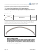
7.2 SFC Field Wiring Schematic
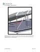
The Chromasun MCT-HT Collector System was designed to simplify installation. There are two
(2) panel-to-panel interconnections between each MCT: The piping interconnection; and the
power-data-ventilation (PDV) interconnection. At the end of each MCT string there is a junction
box. This junction box makes it so that bare wire can be used for the homeruns between the
MCT string and the Chromasun SFC. As the units were designed to be hermetically sealed, it is
important to do all of the ventilation/wiring connections at the same time to maintain the
interior of the panel. Avoid performing these interconnections on humid days or when there is
standing water on the rooftop. MCT-HT units should always be able to vent the air inside;
otherwise there could be pressure build-up or vacuum pressure inside the unit which could
cause damage.
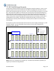
For the panel-to-panel connections PDV interconnects are used to supply ventilating air, as well
as power and data. For each individual string a homerun from the SFC will provide the
ventilation, power, and data.
1.01 1.02 1.03 1.04 1.05 1.06 1.07 1.101.091.08
2.01 2.02 2.03 2.04 2.05 2.06 2.07 2.102.092.08
3.01 3.02 3.03 3.04 3.05 3.06 3.07 3.103.093.08
Field Controller
J1
J2
J3
SFC String A
SFC String B
SFC String C
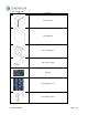
Legend
1
A
1
0
J1
MCT-HT
String Junction Box
PDV Homerun
PDV Connection
Figure 13: 3 rows of 10 MCT's in series connected to a Desiccant box and Field Controller
NOTE: The set up is intended as an example only. The field Layout should be specified by an
engineer per Chromasun Design Manual.