
Installation manual


PVT-MCT10A-EN Page | 12
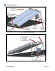
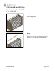
Figure 8: MCT Side View
NOTE: The MCT angle and corresponding height of the rear leg vary depending on site location.
The designing engineer should specify the panel angle and the distance between rows
to avoid shading. The Chromasun MCT Design Manual should be referenced for more
detailed information. For reference, Table 2 shows Unistrut spacing based on collector
slope.
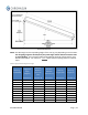
Table 2: Appropriate MCT Angle and Length
MCT Leg
Stand Model
Suggested
Angle
(degrees)
Distance
Between
Unistruts
(mm)
Distance
Between
Unistruts (in)
Rear Leg
Length (mm)
Rear Leg
Length (in)
Dimension A
Dimension B
Dimension B
Dimension C
Dimension C
0
0
3244
128
0
0
5
5
3232
127
283
11
10
10
3195
126
563
22
15
15
3133
123
840
33
20
20
3048
121
1110
44
25
25
2940
116
1371
54
30
30
2809
111
1622
64
35
35
2657
105
1861
73
40
40
2485
98
2085
82
45
45
2294
90
2294
90