.1.1.
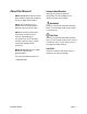
About the Manual NOTE: IMPORTANT! Read this entire manual before beginning installation, wiring, or usage of this product. NOTE: The installation of this equipment must comply with all National, State, and Local Codes. NOTE: By carefully reviewing the information contained in this manual, and following the instructions the risk of: improper operation, personal injury, and/or component damage will be minimized.
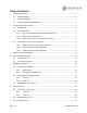
Table of Contents 1 2 General Information ................................................................................................................ 4 1.1 Bulk Packaging .............................................................................................................. 4 1.2 Domestic Shipment ...................................................................................................... 4 1.3 Sling Kit (Recommended Option) ......................................................
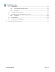
7.1 SFC Hardware ............................................................................................................. 31 7.1.1 SFC PCB with Expansion Board ........................................................................ 31 7.1.2 Parts List........................................................................................................... 32 7.2 SFC Field Wiring Schematic ........................................................................................ 34 7.
What is Included NOTE: Reading through this manual is a necessity. The Chromasun microconcentrator (MCT) High-Temperature Thermal Collector System requires attention to detail for installation. NOTE: The installation of this equipment must comply with all National, State, and Local Codes.
1 General Information 1.1 Bulk Packaging Large orders of MCT panels are shipped in bulk on reusable pallets. The MCTs are integral to the shipping pallet and must be disassembled from the pallet to be unloaded. Additional parts accompany the MCT shipping pallets in standard corrugated packaging. 1.2 Domestic Shipment Units purchased within North America will be shipped via a flat bed truck. The MCT units are stacked in sets of five (5) in reusable wooden pallets.
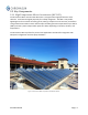
2 The Chromasun MCT System 2.1 Background The Chromasun High-Temperature Thermal Collector System consists of two (2) major components: The MCT High-Temperature Collector (MCT-HT); and the Solar Field Controller. An MCT installation will typically consist of many SFC units connected to one or more Solar Field Controllers. Each SFC can support up to 40 MCTs (4 strings of 10 units each).
2.2 Key Components 2.2.1 High Temperature Micro-Concentrator (MCT-HT) The Chromasun Micro-Concentrator MCT-HT is a next generation high performance solar collector. It has been designed purposely for rooftop integration. The MCT is low profile, lightweight and has no external moving parts; making it simple to mount and easy to maintain. Using a 20X concentration Fresnel reflector optic the MCT generates temperatures up to 200°C (400°F) and has a power output which peaks at 2.
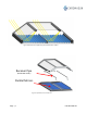
Figure 4 Schematic of sunlight being concentrated within an MCT Receiver Pipe (SS 304 A213 Tube) Parallel Mirrors Figure 3 Exploded view of an MCT-HT Page | 7 PVT-MCT10A-EN
2.2.2 Solar Field Controller (SFC) A Chromasun installation will feature one or more Solar Field Controllers, which serve as the supervisory controller to the individual MCT units. Each MCT SFC can connect up to four (4) strings of ten (10) MCT Collectors, for a total of 40 MCT Collectors per SFC. Additional MCT Field Controllers can be connected to increase the number of panels controlled in the system.
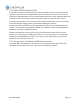
2.3 Optional/Recommended Components 2.3.1 Mount Legs (set of 2 per MCT) (Optional) Our Mount Legs enable installation of the MCT at the recommended angle from a flat base. A flat base built from Unistrut (or similar structure) is required. The mounting portion of this manual was written for use with our Mount Legs. If you choose to not use our Mount Legs please consult an engineer for an alternative method. These can be seen below in Figure 5 and Figure 6. 2.3.
Figure 5: Components from Front View Figure 6: Components from Rear View PVT-MCT10A-EN Page | 10
3 Measurements and Weights Table 1: Physical Characteristics Dimensions Weight Unit Area Weight per Unit Area Weight per Unit Unistrut See Diagrams Below 100 kg 4.23 m2 24 kg/m2 38 kg/m 220 lb 45 sq. ft. 4.9 lb/sq. ft.
Figure 8: MCT Side View NOTE: The MCT angle and corresponding height of the rear leg vary depending on site location. The designing engineer should specify the panel angle and the distance between rows to avoid shading. The Chromasun MCT Design Manual should be referenced for more detailed information. For reference, Table 2 shows Unistrut spacing based on collector slope.
4 Pre-Installation Checklist 4.1 Inventory Check Make sure that all the units are present Check the containers to make sure they were not mistreated or damaged Inspect the MCT’s for any distortions such as: o Shattered Glass o Cracks o Obvious Bends o Collapsed/Bent Terminals 4.
5 Rigging & Installation 5.1 Unpacking the MCT-HT 5.1.1 Wood Pallet Step 1. The shipping pallet. Step 2. Remove the two top cross bars which are held down by 4X 2.5” #10 wood screws.
Step 3. Remove the two triangle pieces from one side of the crate only to maintain structural stability. Each side is held in place by 13X 2.5” #10 wood screws. (26 total) Step 4. Remove the two rectangular end pieces. Each end piece is held in place by 2X 2.5” #10 wood screws. As well as 2X 2” 3/8” hex cap bolts. Step 5. Crane the MCT unit away by connecting to the 4 lifting holes located at each corner of the MCT.
Repeat steps 3 through 5 until all the MCT’s are removed PVT-MCT10A-EN Page | 16
5.1.2 Collapsing the Wood Pallet Step 1. Arrange the pieces as shown below. One row of end pieces fit nicely into the grooves between the horizontal slats in the pallet. The remaining 4 end pieces are arranged on top of the end pieces already on the pallet, upside down to interlock. The two triangle gussets are laid down on top of the end pieces, and the top cross bars are laid down on top of that. Step 2. The finalized Collapsed Wood Pallet.
Step 3. The Wood Pallets can be stacked on top of each other when ready to be shipped back to Chromasun. Step 4. The Pallets ready to be shipped back.
5.2 Lifting and Mounting the MCT’s This section of the MCT-HT installation manual was written for the optional mounting kit which includes the MCT Stand Legs, and the MCT Stand Clamps. If these additional items were not purchased then please consult an engineer about alternate options.
5.2.1 Parts List Part Part Name Quantity MCT w/ Mount Legs Refer to Order MCT Stand Clamp Refer to Order ½” Unistrut Nut Refer to Order ½” Unistrut Bolt Refer to Order 5.2.
5.3 MCT Mounting Procedure Step 1. Make sure that the Unistrut is laid down parallel to each other. Step 2. Loosen the short leg slightly so that it is able to swing down (needs to be loosened on both sides). Step 3. Lower the MCT panel onto the Unistrut so that the short leg is properly seated around the channel. The long leg can remain folded in its resting position.
Step 4. Clamp down the front of the MCT using a strut nut, a stand clamp, a washer, and a bolt. Step 5. Place the next MCT down using the same methods described for the first MCT. Step 6. After lowering the next MCT, place two spacer wedges between the MCT’s taking caution to not place the blocks on the weld so that the blocks are seated flush. Then push the next MCT up against the previous MCT. Taking caution not to push too hard, but just enough so that the MCT’s are butted up against the spacer blocks.
Step 7. Clamp down the front of the MCT’s using a strut nut, a stand clamp, a washer, and a bolt.
Repeat Steps 5 through 7 until MCT row is complete PVT-MCT10A-EN Page | 24
Step 8. Lift the back of the MCT up (The end with the long leg). Step 9. Loosen the long leg so that it can swing down into position. Then set the strut in the channel for the long leg like the short leg. When the Legs are set tighten up both the front and the back legs! Step 10. Clamp down the back of the MCT’s using a strut nut, a stand clamp, a washer, and a bolt.
Step 11. Place a spacer block and slide the 2nd MCT over to make sure that it is still seated tightly against the 1st MCT. Step 12. Clamp down the back of the MCT’s using a strut nut, a stand clamp, a washer, and a bolt.
Repeat Steps 8 through 12 until MCT row is complete Page | 27 PVT-MCT10A-EN
6 MCT Plumbing 6.1 Piping Inter-Connection The piping system must be designed by a certified engineer and is to follow National, State, and Local codes. The Chromasun MCT Design Manual should be referenced to assist with hydronic design. This section was written to be used with our recommended Chromasun header Piping Kit. If this option was not purchased please consult an engineer for alternate solutions.
Figure 9: MCT Piping Interconnect NOTE: For parallel connections, have the MCTs plumbed to a manifold (not provided) and then follow the piping outlined in the Basis of Design (BOD) document. The included steel pipes are to be welded to the heating fluid pipes (receivers) on the MCT. Figure 10: MCT Piping Interconnects.
6.2 Header Connections Header Connection Header Connections are beyond the scope of this manual. Please consult an engineer for an approved solution. A section is included in the Chromasun Design Manual with additional suggested connection methodologies.
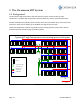
7 Solar Field Controller 7.1 SFC Hardware Power Supplies SFC PCB SFC Expansion Board Figure 11: Open SFC 7.1.
7.1.
SFC_Power Supply_DC_Jumper SFC_Common_Wire_Jumper SFC_Live_Wire_Jumper Page | 33 PVT-MCT10A-EN
7.2 SFC Field Wiring Schematic The Chromasun MCT-HT Collector System was designed to simplify installation. There are two (2) panel-to-panel interconnections between each MCT: The piping interconnection; and the power-data-ventilation (PDV) interconnection. At the end of each MCT string there is a junction box. This junction box makes it so that bare wire can be used for the homeruns between the MCT string and the Chromasun SFC.
For the Homerun Layout and material selection, consult the field design layout provided by the design engineer. Otherwise consult the Chromasun field design white paper. 7.3 Power/Data/Ventilation (PDV) Interconnects The MCT’s may come shipped with desiccants attached to the ventilation ports. These are not to be removed until the SFC and SFC wirings are completed.
Step 1: Unseal the Power-Data- Port Figure 15: Sealed Power-Data Port PVT-MCT10A-EN NOTICE: Equipment Damage! Do not unseal the Power-Data port until ready to install. The interior of the MCT is designed for indoor conditions. By opening the Power-Data port, the interior of the MCT is exposed to the outdoor elements. If any foreign objects (i.e. moisture, mold) get inside they may heavily damage the MCT.
Step 2: Have the Power-Data Interconnect ready Figure 16: Cable and Port Step 5: Connect the Power and Data cables Figure 17: Aligned Power and Data Cables Step 6: Securely fasten the conduit into the conduit fitting Figure 18: Sealed Cable to Port Page | 37 PVT-MCT10A-EN
7.4 Junction Boxes The Chromasun Junction Boxes were designed to simplify installation of Chromasun HT System. A Chromasun Junction Box connects an MCT String to the Chromasun SFC. This makes it so that bare wire can be used for the homeruns. The wire is connected to the junction panel inside of the Chromasun SFC. The bare wire is then run inside of an appropriate conduit specified in the design layout. The bare wire terminates in the string end Chromasun Junction box.
7.5 SFC Expansion Board Signals 4 5 3 4 3 FS 2 2 1 1 Figure 19: SFC Expansion Board Inputs (Red) (Do NOT Connect – Consult Commissioning Documentation) 1. 2. 3. 4. 5. SF. Heat Request Signal Solar Resource Signal MCT Attenuate Signal UPS Signal Unused (Jumper) Flow Switch Outputs (Blue) 1. 2. 3. 4. Pump/signal to BMS for solar pump Desiccant System Desiccant System Desiccant System NOTE: If your system does not have a component, confirm with your Chromasun customized order.
Desiccant Setup 8 Desiccant Ventilation Hardware During normal operation, the air within the MCT-HT will expand and contract. In order to preserve the environment within the MCT-HT units during this “breathing”, Chromasun has engineered an active desiccant system. The active desiccant system is included as part of the Solar Field Controller and operates automatically without need for configuration or maintenance. Details on this system are not included in this manual.