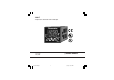
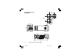
604-7 Temperature Controller with mA Output Chromalox 1604 r USER'S MANUAL Issue date May 2000 1604-7-0-AB.
CONTENTS MOUNTING REQUIREMENTS ........................... 1 OUTLINE AND CUT OUT DIMENSIONS ........... 2 CONNECTION DIAGRAMS ................................ 3 PRELIMINARY HARDWARE SETTINGS ........... 9 CONFIGURATION PROCEDURE .................... 10 OPERATIVE MODE .......................................... 18 Display function .......................................... 18 Indicators ...................................................
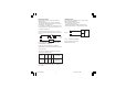
Model identification Model 1604 1/16 DIN Temperature Controller Code 7 Output 1 - Heat or Cool 20 mA Output Code 1 Output 2 - Alarm Relay, 2 Amp at 250 VAC (Resistive load) Code 0 None 1 Out #3, 2 Amps at 250 V AC (Resistive load) 2 Heater Break Down input, Out #3 3 RS 485 Digital communications, Out #3 4 RS 485 Digital comm.
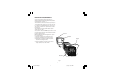
MOUNTING REQUIREMENTS Select a mounting location where there is minimum vibration and the ambient temperature range between 0 and 50 °C. The instrument can be mounted on a panel up to 15 mm thick with a square cutout of 45 x 45 mm. For outline and cutout dimensions refer to Fig. 2. The surface texture of the panel must be better than 6,3 mm. The instrument is shipped with rubber panel gasket (50 to 60 Sh).
3.0 (75) OUTLINE AND CUT OUT DIMENSIONS 2.4 (60) 1.77 (45) 1.9 (48) 1.77 (45) 2.2 (56) 4.8 (122) Fig. 2 OUTLINE AND CUT-OUT DIMENSIONS 2 1604-7-1-AB.
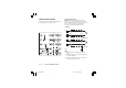
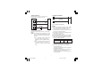
A) MEASURING INPUTS NOTE: Any external components (like zener barriers etc.) connected between sensor and input terminals may cause errors in measurement due to excessive and/or not balanced line resistance or possible leakage currents. CONNECTION DIAGRAMS Connections are to be made with the instrument housing installed in its proper location. TC INPUT + 10 _ 9 Shield + 10 _ 9 Shield Fig. 4 NOTE: 1) Don’t run input wires together with power cables.
LINEAR INPUT RTD INPUT RTD 10 RTD + _ 9 mA, mV or V Shield + 10 8 9 10 8 9 10 _ 9 Fig. 5 RTD INPUT WIRING G NOTE: 1) Don’t run input wires together with power cables. 2) Pay attention to the line resistance; a high line resistance may cause measurement errors. 3) When shielded cable is used, it should be grounded at one side only to avoid ground loop currents. 4) The resistance of the 3 wires must be the same. Fig.
B) LOGIC INPUT Safety note: 1) Do not run logic input wiring together with power cables. 2) Use an external dry contact capable of switching 0.5 mA, 5 V DC. 3) The instrument needs 100 ms to recognize a contact status variation. 4) The logic inputs are NOT isolated by the measuring input C) RELAY OUTPUTS 1 NO - OUT 2 OUT 2 3 OUT 3 2 NO - OUT 3 C - OUT 2 and 3 Fig. 8 RELAY OUTPUTS WIRING The contact rating of the OUT 2, 3 is 2A/250V AC on resistive load.
LINEAR OUTPUT This instrument is equipped with one linear output (OUT 1) programmable as: - main output (heating or cooling) - secondary output (cooling) - analog retransmission of the measured value - analog retransmission of the operative set point. + 6 The same problem may occur when a switch is used in series with the internal contacts as shown in Fig. 9. C R OUT 1 _ 7 POWER LINE Fig. 10 mA OUTPUT WIRING LOAD It is an isolated analog output. Maximum load: 500 W. Fig.
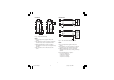
D) POWER LINE WIRING SERIAL INTERFACE RS-485 interface allows to connect up to 30 devices with one remote master unit. 12 13 A'/A A/A' B'/B B/B' COMMON M A S T E R 5 R (S,T) Fig. 12 POWER LINE WIRING NOTES: 1) Before connecting the instrument to the power line, make sure that line voltage corresponds to the description on the identification label. 2) To avoid electrical shock, connect power line at the end of the wiring procedure.
NOTE: a single switch or circuit-breaker can drive more than one instrument. 9) When the NEUTRAL line is present, connect it to terminal 4. 8 1604-7-1-AB.
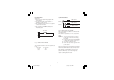
OPEN INPUT CIRCUIT This instrument is able to identify the open circuit for TC and RTD inputs. The open input circuit condition for RTD input is shown by an "overrange" indication. For TC input, it is possible to select overrange indication (standard) or underrange indication setting the CH101 and SH101 according to the following table: Overrange (STD) CH101 = close SH101 = open Underrange CH101 = open SH101 = close PRELIMINARY HARDWARE SETTINGS 1) Remove the instrument from its case.
SEr3 = Baude rate for serial link Not available when SEr1 = OFF From 600 to 19200 baud. NOTE: 19200 baud is shown on display as 19.2. GENERAL NOTES for configuration. FUNC = This will memorize the new value of the selected parameter and go to the next parameter (increasing order). MAN = This will scroll back the parameters without memorization of the new value. s = This will increase the value of the selected parameter t = This will decrease the value of the selected parameter.
the input range. When this parameter is modified, rH parameter will be re-aligned to it. The initial and full scale values determine the input span which is used by the PID algorithm, the SMART and the alarm functions. 21 = TC type J range -150 / +1830 °F 22 = TC type K range -150 / +2500 °F 23 = TC type T range -330 / +750 °F 24 = TC type N range -150 / +2550 °F 25 = TC type R range 0 / +3200 °F 26 = TC type S range 0 / +3200 °F 27 = RTD type Pt 100 range-199.9 / +400.
L.A. = Low alarm (inside for band alarm) with automatic reset (latched). H.L. = High alarm (outside band) with manual reset (latched). L.L. = Low alarm (inside band) with manual reset (latched). P7 = analog retransmission - initial scale value. Available only when P5 = Pv.rt or SP.rt. It is programmable from -1999 to 4000. The decimal point will be positioned as selected with P2 parameter. P8 = analog retransmission - full scale value. Available only when P5 = Pv.rt or SP.rt.
P16 = Threshold of the “Soft Start” function. Threshold value in eng. units to initiate the "Soft start" function (output power limiting) at start up. Range : within the readout span. NOTE: This threshold value will not be taken into account when tOL = InF. P12 = Alarm 2 operating mode Available only when P11 is equal to "AL2.P", "AL2.b" or "AL2.d". H.A. = High alarm (outside for band alarm) with automatic reset (latched). L.A. = Low alarm (inside for band alarm) with automatic reset (latched). H.L.
P21 = Displayed value of the power output for the secondary control output This parameter is available only when two control outputs are configured. nOrL = the displayed value is equal to the result of PID calculation. CnPL = the displayed value is complemented (100 - PID calculation). NOTE: when two control outputs are configured, the P18 and P19 selections are applied to the "rEv" control output while P20 and P21 selections are applied to the "dir" control output.
NOTE: for more details to stand-by (mask) function, see P25 parameter. P24 = Alarm 1 action Available only when P9 = "AL1.P", "AL1.d" or "AL1.b". dir = direct action (relay energized in alarm condition) rEV = reverse action (relay de-energized in alarm condition) P28 = OFFSET adjustment added to the measured value This parameter allows to set a constant OFFSET throughout the readout range. It is skipped for linear inputs - For readout ranges with decimal figure, P28 is programmable from -19.9 to 19.9.
P31 = Maximum value of the proportional band calculated by the SMART algorithm. This parameter is skipped when none of the outputs is programmed as control output or P30=0. This parameter is programmable from P32 value to 200.0 %. 2 = the instrument starts in the same way it was left prior to power shut down but if the instrument was in manual mode, it will restart with a power output equal to 0.
negative value decreases the low limit of the antireset-wind up (under set point). NOTE: when the instrument detects an out of range condition, it assignes the P38 value to the PID output but P18 and P20 parameter are still active. P43 = Set point indication Fn.SP = during operative mode, when the instrument performs a ramp, it will show the final set point value. OP.SP =during operative mode, when the instrument performs a ramp, it will show the operative set point.
When return in "Normal Display Mode" is desired, push FUNC push-button again. OPERATIVE MODE 1) Remove the instrument from its case. 2) Set the internal dip switch V101 in closed condition 3) Re-insert the instrument. 4) Switch on the instrument. INDICATORS °C Lit when the process variable is shown in Celsius degrees. °F Lit when the process variable is shown in Fahrenheit degrees. SMRT Flashing when the first part of the SMART algorithm is active.
NOTE: a 10 or 30 seconds time out (see P 36) can be selected for parameter modification during run time mode. If, during operative parameter modification, no pushbutton is pressed for more than 10 (30) seconds, the instrument goes automatically to the “normal display mode” and the eventual modification of the last parameter will be lost. Pushbutton functionality during operating mode.
DIRECT ACCESS TO SET POINT When the device is in AUTO mode and in “Normal Display Mode”, it is possible to access directly to set point modification (SP or SP2). Pushing s or t for more than 2 s, the set point will begin changing. The new set point value becomes operative since no pushbutton has been depressed at the end of 2 s timeout. The transfer from AUTO to MANUAL and viceversa is bumpless (this function is not provided if integral action is excluded).
SERIAL LINK The device can be connected to a host computer by a serial link. The host can put the device in LOCAL (functions and parameters are controlled via keyboard) or in REMOTE (functions and parameters are controlled via serial link). The REMOTE status is signalled by the decimal point (labelled REM) at the right hand of the LSD of the upper display. This instrument allows to modify the operative and configuration parameters, via serial link.
OPERATIVE PARAMETERS Push the FUNC pushbutton, the lower display will show the code while the upper display will show the value or the status (On or OFF) of the selected parameter. By s or t pushbutton it is possible to set the desired value or the desired status. Pushing the FUNC pushbutton, the instrument memorizes the new value (or the new status) and goes to the next parameter. Some of the following parameter may be skipped according to the instrument configuration. AL1 Param.
HyS ti td IP Cy2 Note:When device is working with SMART algorithm the Pb value will be limited by P31 and P32 parameters. Hysteresis for ON/OFF control action This parameter is available only when Pb=0. Range: from 0.1% to 10.0% of the input span. Integral time This parameter is skipped if Pb=0 (ON/ OFF action). Range: from 00.01 to 20.00 [mm.ss]. Above this value the display blanks and integral action is excluded.
Grd1 Grd2 OLH tOL rnP Ramp applied to an increasing set point change Range: from 1 to 100 digits per minute. Above this value the display shows “InF” meaning that the transfer will be done as a step change. Ramp applied to a decreasing set point changes For other details see Grd1 parameter. Output high limit Range: - From 0.0 to 100.0 % of the output span when device is configured with one control output. - From -100.0 to 100.0% of the output span when device is configured with two control outputs.
When P37 is different from zero and an out of range condition is detected, the instrument operates in accordance with P37 and P38 parameters. ERROR MESSAGES OVERRANGE, UNDERRANGE AND SENSOR LEADS BREAK INDICATIONS The device is capable to detect a fault on the process variable (OVERRANGE or UNDERRANGE or SENSOR LEADS BREAK).
ERROR LIST SEr Serial interface parameter error. 100 Write EEPROM error. 150 CPU error. 200 Tentative to write on protected memory. 201 - 2xx Configuration parameter error. The two less significant digits shown the number of the wrong parameter (ex. 209 Err shows an Error on P9 parameter) 299 Error on control output selection. 301 Selected input calibration error 307 RJ input calibration error 320 Analog retransmission calibration error.
EN 50081-2 and EN 50082-2) and to council directives 73/23/EEC and 93/68/EEC (reference harmonized standard EN 61010-1). Installation category: II Temperature drift: (CJ excluded) < 200 ppm/°C of span for mV and TC ranges 1, 3, 5, 7, 20, 21, 22, 24. < 300 ppm/°C of span for mA/V < 400 ppm/°C of span for RTD range 11, 28 and TC range 0, 2, 4, 6, 23. < 500 ppm/°C of span for RTD range 10 and TC ranges 8, 9, 25, 26. < 800 ppm/°C of span for RTD range 27. Operative temperature: from 0 to 50 °C.
C) LINEAR INPUTS Read-out: keyboard programmable between -1999 and +4000. Decimal point: programmable in any position. Burn out: the instrument shows the burn out condition as an underrange condition for 4-20 mA, 1-5 V and 2-10 V input types. It shows the burn out condition as an underrange or an overrange condition (selectable by soldering jumper) for 0-60 mV and 12-60 mV input types. No indication are available for 0-20 mA, 0-5 V and 0-10 V input types.
SMART: keyboard enabling/disabling Auto/Manual: selectable by front pushbutton. Auto/Manual transfer: bumpless method type Indicator "MAN" : OFF in auto mode and lit in manual mode. SET POINTS This instrument allows to use 2 set points: SP and SP2. The set point selection is possible only by logic input.
OUTPUT 3 Type: relay with SPST contact with rated current 2 A at 250 V AC on resistive load. Function: programmable as: - control output (heating or cooling) - Alarm 2 output. Output cycle time (when used as control output) programmable from 1 s to 200 s. Output level limiter: - For one control medium: from 0 to 100 % . - For two control mediums: from -100 to +100 %.
SUPPLY TERMINALS AND FROM RELAY OUTPUT TERMINALS 2) Remove the instrument from case. 3) Using a vacuum cleaner or a compressed air jet (max. 3 kg/cm2) remove all deposit of dust and dirt which may be present on the louvers and on the internal circuits trying to be careful for not damage the electronic components.
APPENDIX A DEFAULT PARAMETERS DEFAULT OPERATIVE PARAMETERS The control parameters can be loaded with predetermined default values. These data are the typical values loaded in the instrument prior to shipment from factory. To load the default values proceed as follows: a) The internal switch should be closed. b) The SMART function should be disabled. c) The upper display will show the process variable while the lower display will show the set point value.
DEFAULT CONFIGURATION PARAMETERS The configuration parameters can be loaded with predetermined default values. These data are the typical values loaded in the instrument prior to shipment from factory. To load the default values proceed as follows: a) The internal switch (V101, see fig. 13) should be open. b) The upper display will show: COnF c) Push the t pushbutton; the display will show the firmware version. COnF A. 0 0 d) Maintaining the pressure on the t pushbutton push the s pushbutton also.
P29 P30 P31 P32 P33 P34 P35 P36 P37 P38 P39 P40 P41 P42 P43 P44 On 2 30.0 1.0 00.20 On 0 10 0 0.0 nO.FL nO.FL Pid 10.0 Fn.Sp 0 On 2 30.0 1.0 00.20 On 0 30 0 0.0 nO.FL nO.FL Pid 10.0 Fn.Sp 0 Appendix A.3 1604-7-A-AB.
Appendix A.4 1604-7-A-AB.
170.IU0.160.400 Chromalox® INSTRUMENTS AND CONTROLS 1382 HEIL QUAKER BOULEVARD LAVERGNE, TN 37086-3536 PHONE (615) 793-3900 FAX (615) 793-3563 WIEGAND INDUSTRIAL DIVISION EMERSON ELECTRIC CO. Appendix A.5 1604-7-A-AB.