
Unit installation

5
WIRING
ELECTRIC SHOCK HAZARD. Be sure electricity is
turned off at main switch first before wiring. Any in-
stallation involving electric heaters must be effective-
ly grounded in accordance with the National Electrical
Code to eliminate shock hazard.
1. Use heater only on the voltage and frequency specified on the name-
plate.
2. All wiring should be done in accordance with local codes and the
National Electrical Code by a qualified person as defined in the NEC.
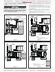
3. Two knockouts are provided on the back of the heater for wire entry.
See Figure 4 for location of knockouts.
4. Branch circuit wire for connection to heater must be at least 60˚C
wire.
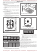
5. The bottom access door is hinged. There are two screws that must be
removed to gain access (Figure 3).
6. A ground wire or ground lug is provided near the power connection
point (ground Wire on HVH-02 to HVH-20 and ground lug on HVH-
25 to HVH-50).
7. Terminals on contactor or on line voltage terminal block are supplied
to be connected to accept the correct size power supply wire. Copper
rated at 600V and 60˚C is satisfactory for the heater branch circuit.
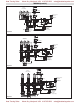
8. Electrical accessories, either kits or factory-installed options, are
shown connected by a dash line on the heater wiring diagram.
9. Wiring connections are to be made on designated wire leads as
shown in the wiring diagrams located inside the access door.
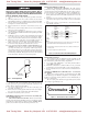
10. Louver adjustment (Do not attempt to adjust while heater is op-
erational): Louvers have been preset at factory with the minimum
open angle. Decreasing the 45˚ angle may result in high tempera-
tures and functioning of the over temperature control. To increase the
opening angle, grasp the left end of louver with the left hand using
the index finger and thumb. Grasp right end of louver with right hand
in the same manner. Twist louver to the desired position.
Top of Heater
45˚ Min.
All Louvers
Figure 7 - Louver Adjustment
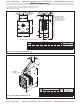
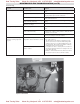
POWER DISCONNECT SWITCH
(Available as a kit or factory installed option). This switch discon-
nects the power to the power leads when the handle is turned to its off
position. Refer to Instruction Sheet PF207.
1. Use copper conductor supply wire only when connecting to the
power line. (See Figure 8.)
2. Connection to the switch pigtails should be made with compres-
sion connectors and the joint should be then well insulated.
3. Consult the local wiring code in your area.
SUMMER FAN SWITCH - Refer to Instruction sheet PF205 with-
out relay, PF206 with relay.
(MOUNTED ON FRONT OF HEATER). When the switch handle is
pointing toward the Summer (Fan ON) position, the fan will run continu-
ously. When the switch handle is pointing toward the WINTER (HEAT)
position, the fan will run only when the heating elements are hot.
REMOTE SUMMER FAN SWITCH
(MANUAL SWITCH-LINE VOLTAGE). The wall switch is
packed in the wiring compartment. The remote fan switch is mounted
external and remote from the HVH unit heater. The voltage of the re-
mote fan switch is the same as the supply voltage to the HVH heater.
1. Use 14 gauge copper, NEC Class 1, 600V rated insulated wire.
Wiring must meet all Local and NEC requirements for 480-volt
service.
2. Install the remote fan switch in standard wall box in any conve-
nient location that is protected from traffic or other accidental dam-
age.
3. Connect the 14 gauge copper field wire to the switch lead wires
with suitable connectors.
Power
Disconnect
Switch
L1
L2
L3
S1
S2
S3
See Notes
Contactor
or Terminal
Block
To
Power
Supply
See
Note 2
Notes:
1. This illustration shows wiring hook up for three phase service. Remove lead
wires marked L3 and S3 when using single phase power service.
2. For units without contactors, disconnect switch is to be wired to terminal block
on heater power.
3. Use copper supply wire only with this switch.
Figure 8 - Power Disconnect Switch Wiring Diagram
REMOTE FAN SWITCH
480V + Heaters require an additional fan relay. (Available as a kit
or factory installed option and standard on heaters 20kW and above).
The wall switch is packed in the wiring compartment.
1. Use 18 gauge (min.) NEC Class 1, 600V wiring that meets all Lo-
cal and NEC requirements.
2. Install the wall switch in a standard wall box in any convenient
location that is protected from traffic or other accidental damage.
3. Connect the field wire to the switch lead wires with suitable con-
nectors.
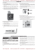
OPTIONAL THERMOSTAT (HVH-TK) Refer to Instruction
Sheet PF204.
Heaters can be equipped with an optional thermostat of the Bulb
and Capillary type for automatic temperature control (Figure 8). The
thermostat controls the heating elements and fan simultaneously to
achieve set temperature.
The “Lo” setting of the thermostat is approximately 40˚F, and the
“Hi” setting is approximately 90˚F.
Chromalox
Figure 9 — Thermostat Location, Front View
Heat Tracing Sales Mount Airy, Maryland USA 410-795-2223 sales@heattracingsales.com
Heat Tracing Sales Mount Airy, Maryland USA 410-795-2223 sales@heattracingsales.com