
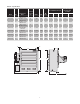
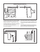
Specifications


9
Refer to Nameplate
for Input Voltage
1PH
L1 L2
Optional
Disconnet
Switch
GND
Optional Aux. Cont.
L1 L2 L3
Heater
Contactor
X1
H1
H2
X2
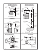
Primary
Secondary
Control Transformer
Refer to Nameplate for Primary (Input)
and Secondary (Control) Voltage.
Built-In or
External
Thermostat
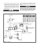
Connect Thermostat Wires
to the Common and Normally
Closed Terminals of One Pole
on the Thermostat.
Remove this Wire when
Using Thermostat
T3
T2
T1
Optional Alarm
Optional
Elements
Manual Reset
High Limit
Auto Reset
High Limit
Motor
1PH
R
Motor
Contactor
L2 L1
(Red)
Fan
(Heat)
White
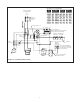
Diagram II - 1 PH Wiring with Fan Switch
Transformer Color Code Tabulation
PRI
VOLT.
PRI. XFMR
LEAD CLRS.
120V SEC
LEAD CLRS.
24V SEC
LEAD CLRS.
H1 H2 X1 X2 X1 X2
208 BLK RED BLK WHT YEL BLU
240 BLK ORG BLK WHT YEL BLU
380 BLK VIO BLK WHT YEL BLU
415 BLK YEL BLK WHT – –
415 BLK BRN – – YEL BLU
480 BLK BLK/RED BLK WHT YEL BLU
575/600 BLK GRY BLK WHT YEL BLU