
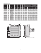
Specifications


8
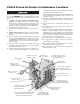
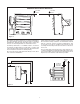
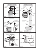
9. Protection against overheating is provided by a high
temperature cutout located within the heat exchanger
wiring compartment. (Figure 9) Activation of the control
will open the control circuit and energize the pilot lamp (if
supplied). If normal airflow is restricted, or stopped, the
unit will be cycled off by the high temperature cutout. The
high temperature cutout is also designed to shut down
the unit completely if the fluid level is low or other heater
malfunction occurs.
High Temperature cutout(s) must never be bypassed
in the control circuit. If the limit actuates, shut down
unit and investigate cause of abnormal operation.
Do not reenergize until the problem has been cor-
rected.
Users should install adequate back-up controls and
safety devices with their electric heating equipment.
If the back-up controls are to be located in the haz-
ardous area, they must be approved for use in the
class of location. Where the consequences of failure
may be severe, back-up controls are essential.
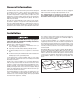
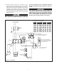
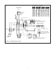
Refer to Nameplate
for Input Voltage
1PH
L1 L2
Optional
Disconnet
Switch
GND
Optional Aux. Cont.
L1 L2 L3
Contactor
X1
H1
H2
X2
Primary
Secondary
Control Transformer
Refer to Nameplate for Primary (Input)
and Secondary (Control) Voltage.
Built-In or
External
Thermostat
Connect Thermostat Wires
to the Common and Normally
Closed Terminals of One Pole
on the Thermostat.
Remove this Wire when
Using Thermostat
T3
T2
T1
Optional Alarm
Optional
Elements
Manual Reset
High Limit
Auto Reset
High Limit
Motor
1PH
Terminal
Block
R
Diagram I - 1 PH Wiring
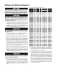
Transformer Color Code Tabulation
PRI
VOLT.
PRI. XFMR
LEAD CLRS.
120V SEC
LEAD CLRS.
24V SEC
LEAD CLRS.
H1 H2 X1 X2 X1 X2
208 BLK RED BLK WHT YEL BLU
240 BLK
ORG BLK
WHT
YEL BLU
380 BLK VIO BLK WHT YEL BLU
415 BLK YEL BLK WHT – –
415
BLK BRN
–
– YEL
BLU
480 BLK BLK/RED BLK WHT YEL BLU
575/600 BLK GRY BLK WHT YEL BLU