
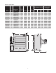
Specifications


4
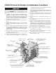
General Information
The CXH-A series units rated 3 through 35 kW are designed
for operation in Class I, Div. 1, Groups C & D and Class II,
Div. 1, Groups E, F and G hazardous atmospheres having
an ignition temperature of 165°C (329°F) or higher. They are
designed for comfort heating and should not be operated in
ambient temperatures exceeding 40°C (104°F). All units in
Table A are UL listed.
The units are easily adapted for wall, ceiling or pole mount-
ing. Refer to Figure 4 on Page XX for mounting information.
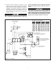
They are supplied with either 24 or 120V internal control cir-
cuit voltage. The heater is designed for use with an external
hazardous location thermostat or optional built-in thermostat.
Standard model CXH-A unit heaters are factory equipped
with an automatic reset type high temperature cutout.
The standard heater is designed to operate up to 7500
feet (2,286m) altitude. Consult factory for specific recom-
mendations when using the units at higher altitudes.
Installation
FIRE/EXPLOSION HAZARD. Mount only in upright po-
sition and observe nameplate mounting clearances.
Heater Location instructions:
Arrange units so their discharge air streams:
A. are subjected to a minimum of interference from col-
umns, machinery and partitions.
B. wipe exposed walls without blowing directly at them.
C. are directed away from room occupants in comfort heat-
ing.
D. are directed along the windward side when installed in a
building exposed to a prevailing wind.
Locate thermostat on interior partition walls or posts away
from cold drafts, internal heat sources and away from heater
discharge air streams.
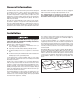
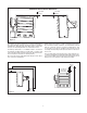
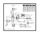
Small rooms can be heated by one unit heater. Where two
walls are exposed, the heater should be mounted as shown
in Figure 2. Large rooms require multi-unit installations. Num-
ber and capacity of units will be determined by volume of
building and square feet of floor area to be heated. Arrange
units to provide perimeter air circulation where each unit sup-
ports the air stream from another.
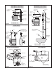
The CXH-A hazardous location heaters are designed for use
only in a permanently mounted upright position. We recom-
mend the use of a mounting kit (ceiling, wall or pole) available
from Chromalox. (Figures 5, 6 and 7)
The ceiling or wall mounting surface and the anchoring provi-
sion must be sufficient to support the combined weights of
the unit and mounting hardware.
If using mounting hardware or a supporting structure not
supplied by Chromalox, the unit should be suspended from
the supporting structure thru the two mounting points on top
of the unit with 5/8 NC bolts and lockwashers. If single point
mounting is desired, order the correct size Chromalox adapt-
er bracket (P/N
027-302361-001 for 12” fan units, P/N 027-302361-002 for
16” fan units) and P/N 027-302361-003 for 20” fan units. This
bracket is designed to hold the unit over its center of gravity
with a 1 dia. bolt. The maximum tilt angles as shown in Figure
3 must not be exceeded in either direction during operation
and installation. Failure to comply will cause high limit shut
down.
EXPOSED
EXPOSED
EXPOSED
EXPOSED
EXPOSED
EXPOSED
Figure 2