
User manual


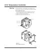


Table of Contents
1–Quick Setup ........................................................................................1
2–Introduction ........................................................................................2
3–Installation and Wiring ........................................................................4
4–Adjusting Setpoint and Configuration ..............................................12
5–Controller and Alarm Operation ........................................................16
6–Replacing Output Modules ............................................................... 17
7–Calibration ........................................................................................19
8–Specifications ...................................................................................21
9–Troubleshooting ................................................................................22
Manual Sections
Illustrations
iii
1.1 Dip Switch Settings ........................................................................1
1.2 Establishing the Set Point ..............................................................1
1.3 Adjusting the Set Point ................................................................... 1
2.1 Front Panel Identification ...............................................................2
2.2 Typical Application .........................................................................3
2.3 Model Identification ........................................................................ 3
3.1 Default Dip Switch Settings ...........................................................4
3.2 Removing Mounting Collars ...........................................................5
3.3 Mounting Dimensions ....................................................................6
3.4 Mounting the 2110 .........................................................................6
3.5 Wiring Terminal Identification .........................................................7
3.6 Thermocouple Connections with Shield ........................................8
3.7 Three-Wire RTD Connections with Shield ......................................9
3.8 Two-Wire RTD Connections ...........................................................9
3.9 Control Output Wiring–R1 and S0 ................................................10
3.10 Control Output Wiring–R3 ............................................................10
3.11 Control Output Wiring–V0 ............................................................10
3.12 Control Output Wiring–S1 and S2 ................................................11
3.13 90-260 VAC Instrument Power Connections ...............................11
3.14 Alarm Connections .......................................................................11
4.1 Establishing the Set Point ............................................................12
4.2 Adjusting the Set Point ................................................................. 12
4.3 Configuring 2110 ..........................................................................13
4.4 Configuring 2110 ..........................................................................13
4.5 Configuring 2110 ..........................................................................13
4.6 Configuring 2110 ..........................................................................13
4.7 Configuring 2110 ..........................................................................13
4.8 Configuring 2110 ..........................................................................13
6.1 Replacing Output Module ............................................................18