
Installation guide


© National Instruments Corporation 9 BNC-2110 Installation Guide
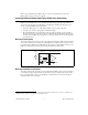
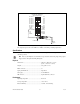
Using the USER 1 and USER 2 BNC Connectors
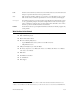
The USER 1 and USER 2 BNC connectors allow you to use a BNC connector for a digital or timing I/O
signal of your choice. The USER 1 and USER 2 BNC connectors are routed (internal to the BNC-2110)
to the USER 1 and USER 2 spring terminals, as shown in Figure 4.
Figure 4. USER <1..2> BNC Connections
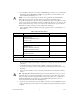
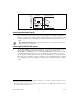
Figure 5 shows an example of how to use the USER 1 and USER 2 BNCs. To access the PFI 8 signal
from a BNC, connect USER 2 on the spring terminal block to PFI 8/P2.0 with a wire.
USER 2 BNC
Internal
Connection
USER 1 BNC
D GND
DIGITAL AND TIMING I/O
Spring Terminal Block
PFI 9/P2.1
PFI 8/P2.0
PFI 7/P1.7
PFI 6/P1.6
PFI 5/P1.5
PFI 4/P1.4
PFI 3/P1.3
PFI 2/P1.2
PFI 1/P1.1
D GND
USER 2
PFI 14/P2.6
+5V
+5V
D GND
P0.7
P0.6
P0.5
P0.4
P0.3
P0.2
P0.1
P0.0
PFI 13/P2.5
D GND
USER 1
PFI 11/P2.3
PFI 10/P2.2
AI SENSE
AI GND
Internal
Connection