
Installation guide


© National Instruments Corporation 7 BNC-2110 Installation Guide
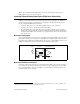
Connecting Trigger/Counter Signals
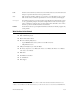
Use the BNC-2110 BNC connectors on the front panel to connect PFI 0/P1.0 (AI START TRIG) and
PFI 12/P2.4 (CTR 0 OUT) signals to your DAQ device. The number of connectors you use depends on
your DAQ device and application. Refer to your DAQ device documentation for information about the
use of these signals. Table 2 describes the trigger/counter BNCs.
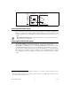
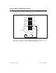
Connecting Digital and Timing I/O Signals
Use the BNC-2110 spring terminal block on the front panel to connect digital and timing I/O signals to
your DAQ device. Refer to your DAQ device documentation for information about the use of these
signals.
When connecting signals to the spring terminals, you can use 28–16 AWG wire with the insulation
stripped to 0.28 in.
Table 3 describes the digital terminals on the front panel of the BNC-2110.
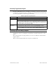
Table 2. Trigger/Counter Signal Descriptions
BNC Description
PFI 0/P1.0 Programmable Function Input channel 0 or Port 1 Digital Input/Output channel 0
AI START TRIG (AI Start Trigger Signal)—As an output, this pin is the ai/StartTrigger
signal. In post-trigger DAQ sequences, a low-to-high transition indicates the initiation of
the acquisition sequence. In applications with pre-trigger samples, a low-to-high transition
indicates the initiation of the pre-trigger samples.
PFI 12/P2.4 Programmable Function Input channel 12 or Port 2 Digital Input/Output channel 4
CTR 0 OUT (Counter 0 Output Signal)—As an input, this pin can be used to route signals
directly to the RTSI bus. As an output, this pin emits the Ctr0InternalOutput signal.