
Installation guide


BNC-2110 Installation Guide 6 ni.com
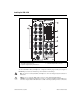
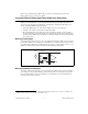
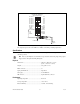
Figure 3. Measuring a Ground-Referenced Signal Source
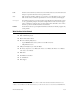
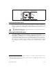
Connecting Analog Output Signals
Use the BNC-2110 BNC connectors on the front panel to connect AO <0..7> signals to your DAQ
device. The number of connectors you use depends on your DAQ device and application. E/M/S Series
DAQ devices can only use the AO <0..1> BNCs.
1
AO Series DAQ devices can use the AO <0..1> and
the AO <2..7> BNCs. Refer to your DAQ device documentation for information about the use of these
signals.
Note (AO Series Devices Only) When using connectors AO <2..7>, you must move the associated
FS/GS switch(es) to the FS position.
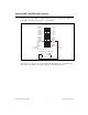
Connecting APFI 0/AO EXT REF Signals
Use the BNC-2110 BNC connectors on the front panel to connect the analog programmable function
interface channel, APFI 0, to your M Series DAQ device or analog output external reference,
AO EXT REF, to your AO/E/S Series device.
2
The AO EXT REF BNC is the external reference input
for the AO circuitry. With some M Series devices, the APFI 0 channel can be used as the external
reference input for the AO circuitry, the external offset for the AO circuitry, or the analog trigger input.
These functions are not available on all devices. Whether you can use this BNC depends on your DAQ
device and application. Refer to your DAQ device documentation for information about the use of these
signals.
1
When using the BNC-2110 with Connector 1 of NI 6229/6259/6289 devices, the AO <0..1> BNCs on the BNC-2110 map to
the AO <2..3> channels on the M Series device.
2
When using the BNC-2110 with Connector 1 of NI 6254/6259/6284/6289 devices, the APFI 0 BNC on the BNC-2110 maps
to the APFI 1 channel on the M Series device.
+
–
Signal
Source
BNC-2110
DAQ Device
(Differential Input Mode)
AI GND
+
–
5 kΩ
0.1 μF
GS
GS Mode