
User manual

Studio Force V 12 / T 12 / D 12 / D XT 12 User Manual 5 V1.3 March 2015
www.chroma
-
q.com
data.
All photometric values listed in this document are based on testing and measurements conducted by certified independent
laboratories with reference to the IES standards.
2. Operation
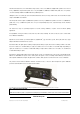
2.1 Unpacking the Units
The Studio Force V 12 / T 12 / D 12 / D XT 12 package includes 1 unit Studio Force 12 fixture, power connector (EU)/power
cord (US) and a Quick Start Guide. We recommend that you keep the original packaging in case the item needs to be returned.
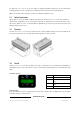
2.2 Cabling
The Studio Force V 12 / T 12 / D 12 / D XT 12 utilise PowerCon connectors for power input and through. The DMX control data
input and through connections from an external control console are via two XLR 5-pin connectors. The chassis are ground
bonded.
Note:
The maximum number of Studio Force V 12 / T 12 / D 12 / D XT 12 fixtures running off a single power input cable is 10
at 120V AC or 20 at 240V AC. Please refer to ANSI and AWG standards for the maximum data and power cable lengths.
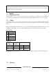
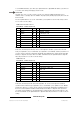
XLR 5-pin Cable:
Pin# Function
1 Ground (Screen)
2 Data Minus
3 Data Plus
4 Spare Data Minus
5 Spare Data Plus
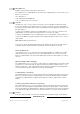
Power Cable:
International
Colour Code
North American
Colour Code
Connections
Green and Yellow Green Earth (E) Ground (Green)
Blue White Neutral (N) Neutral (Silver)
Brown Black Live (L) Hot (Gold)
Important Notice:
The use of an opto-splitter for DMX signal distribution is highly
recommended
when several fixture units are
not
plugged into the same power source.
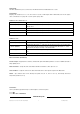
2.3 Mounting