
User`s guide


S
ECTION VII:
Configuring the ENVIRONMENT SENSOR
P-Series Only
Environment Sensor 913-623 @Rev A Section VII, page
1
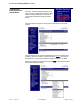
Environment
Sensor
Adhesive
Backed
Velcro Strip
Blue Bus Cable
3m (15’)
ManageUPS with
Blue Bus port
MIBs &
Documentation CD
ManageUPS Net
Adapter P-Series
Environment
Sensor
Kit Components
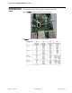
Hardware
Specifications
Single sensor powered from Blue Bus @ 7-24Vdc, < 0.36 watts
Multiple sensors may require an auxiliary power supply.
(Refer to Appendix C: Compatibility Table for ManageUPS Blue Bus Accessories)
Input power
Auxiliary power input accepts 12-24Vdc unregulated.
Connector is 2.5mm center pin.
Outer barrel is positive, inner post is negative.
Temperature Measurement range 0 – 75 degC
Accuracy +/- 1 degC between 10 and 50 degC
Relative Humidity Measurement range 1-99% RH
Accuracy +/- 2% between 10 and 90 %RH
Input Contacts Accepts input from up to three (3) Form C dry contacts
Output Relay 1 relay contact, rated 1A @ 30V (normally open or normally closed)
Environment
Sensor
Conformance Emissions:
EMC Directive 89/336/EEC as amended by 92/31/EEC and 93/68/EEC
EN 55022: 19948+ A1:2000 + A2:2003
EN 50091-2: 1995
EN 61000-3-2:2000
EN 61000-3-3:1995 +A1:2001
Immunity:
EMC Directive 89/336/EEC as amended by 92/31/EEC and 93/68/EEC
EN 55022: 19948+ A1:2000 + A2:2003
EN 50091-2: 1995
EN 61000-4-2:1995 +A1:1998 + A2:2002 (IEC 1000-4-2)
EN 61000-4-3:2002 (IEC 10000-4-3)
EN 61000-4-4:1995 +A1:2001 + A2:2001 (IEC 1000-4-4)
EN 61000-4-5:1995 +A1:2001 (IEC 1000-4-5)
EN 61000-4-6:1996 +A1:2001 (IEC 1000-4-6)
EN 61000-4-8:1993 +A1:2001 (IEC 1000-4-8)
EN 61000-4-11:1994 +A1:2001 (IEC 1000-4-11)
Cable CAT5 STP with RF filter at ManageUPS connection point.
(filtered cable not required for connections between sensors).
Blue Bus
2.5MM