
User`s guide


S
ECTION VI: Configuring Modbus Services
Modbus Services 913-623 @Rev A Section VI, page
3
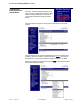
Physical RS485
Network Connection
Use the RJ11 to Screw Terminal adapter provided.
Connect 16
A
WG
(
or smaller
)
conductors from
y
our RS485 network cable as shown
below:
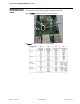
Ground is Pin 1
D+ is connected to Pin 2 and Pin 4
D- is connected to Pin 3 and Pin 5
Pins 4 and 5 are also used in full duplex mode.
Pin 6 is not used
In half Duplex mode Pin(s) 2 & 4 and Pin(s) 3 & 5 are electrically connected to aid
in the wiring of multiple devices on the Modbus network. When the ManageUPS
Net Adapter P-Series is configured for full Duplex Pin(s) 4 & 5 are reassigned to
RXD+ & RXD- respectively.
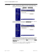
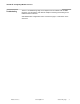
Wiring Diagrams
Half Duplex Wiring Diagram
Full Duplex Wiring Diagram