CHLORIDE User's Guide and Reference ManageUPS® NET ADAPTER P-Series ManageUPS® NET ADAPTER VP Network Adapter for UPS Management Licenses and Trademarks ManageUPS and MopUPS are registered trademarks of ONEAC Corporation, A Chloride Power Protection Company. All other trademarks, product and corporate names are the property of their respective owners. Entire contents copyright ©2008 ONEAC Corporation. All rights reserved. Reproduction in whole or in part without permission is prohibited.
ManageUPS® NET ADAPTER P-SERIES Network Adapter for UPS Management Table of Contents Section I: About ManageUPS Net Adapter P-Series ManageUPS Net Adapter P-Series ManageUPS Hardware options Installation Overview Application Profiles I–1 I–2 I–4 I–5 SNMP Agent .......................................................................................................... 5 E-mail and WEB......................................................................................................
TABLE OF CONTENTS Section V Device Settings – UPS Status Diagnostics Control Configuration About UPS Section VI V–1 V–3 V–4 V–5 V–7 Configuring Modbus Services P-Series Only Modbus TCPIP & Serial Communications Troubleshooting Communications on Serial Networks Physical RS485 Network Connection Configuration for other Serial Communications network MODBUS Register Map License Manager Troubleshooting Section VII VII – 1 VII – 2 VII – 3 VII – 4 VII – 5 VII – 6 VII – 7 Configuring the Environment Sensor
SECTION I: ABOUT MANAGEUPS NET ADAPTER ManageUPS ManageUPS Net Adapter provides a variety of monitoring and management-related services for uninterruptible power systems and associated auxiliary devices. The ManageUPS Net Adapter P-Series include MODBUS Services which provide UPS Status information in MODBUS (JBUS) protocol for direct integration with Building Monitoring Systems. Media supported include RS232, RS422 and RS485 serial protocols and MODBUS IP over Ethernet.
Section I: About ManageUPS ManageUPS Hardware Options The services available on your ManageUPS Net Adapter depend upon hardware options. Connectivity Device Coverage UPS VP 10/100 BaseT Ethernet P-Series 10/100 BaseT Ethernet Legacy Chassis Service Mechanisms Page 2 Section I UPS, Modbus, & Environment Sensor Accessory A legacy conversion card and external chassis enables ManageUPS Net Adapter VP and P-Series hardware options to be compatible with legacy UPS.
SECTION I: ABOUT MANAGEUPS SERVICES1 MECHANISMS Agents, Servers, & Clients P-Series Only BASE HARDWARE C Message C/A SMTP e-mail A SNMP trap MOPNET C/A RCCMD Shutdown Hostname resolution for NTP, SMTP, MopNSA and RCCMD DNS C/S/A Manage Integration: SNMP NMS MopUPS, MopNSA Integration: MopUPSP/R RCCMD C NTP Clock Synchronization S FTP/TFTP Network Update C DHCP Auto Net-Configuration S CONSOLE Dial-in and Local RS232 Terminal access to Configuration and Status menus.
Section I: About ManageUPS Installation Overview There are two parts to the installation of ManageUPS Net Adapter: 1. Hardware Installation ⎯ Physical connection of ManageUPS to your UPS and attachment to the network. Configuration ⎯ Confirm/Adjust network settings and set message triggers and destinations, shutdown targets, network security and other parameters.
SECTION I: ABOUT MANAGEUPS Application Profiles: "The UPS is the critical foundation to my network. If something isn't right ⎯ the NOC (Network Operations Center) needs to know about it." SNMP Agent Network administrators at a central operations center use an SNMP SCENARIO: management system to monitor and manage IT network infrastructure, and associated power/environmental infrastructure.
Section I: About ManageUPS Application Profiles: "In a batch system, everything is entered during the day, but nothing is posted until the 'batch' runs at night. Often time 'jobs' need to be rerun." Email-WEB SCENARIO: The IT administrator for a campus network wants the Help Desk to be aware of any power-fail conditions or UPS service alerts that may impact IT resource availability.
SECTION I: ABOUT MANAGEUPS Application Profiles: "If you know about your downtime, then you can control anything." UPS status server for UPS monitoring software ManageUPS hosts a UPS status server (MopNet server) that allows copies of MopUPS software (MopNet client), installed on network computers to retrieve UPS status information over the network and initiate server-specific responses to power systems events.
Section I: About ManageUPS Application Profiles: "All I need is a simple solution to call graceful shutdown for a few groups of servers." Network Shutdown Controller (NSC) for MopNSA or RCCMD agents. Network shutdown controller Network shutdown agents SCENARIO: An administrator with three sets of servers needs to trade off capacity for uptime in the event of a prolonged AC failure. SOLUTION: Server shutdown agents (MopNSA or RCCMD software) are installed on each server.
SECTION II: NETWORK SETUP Understand Your Network Environment: To determine the simplest configuration method for your network environment, you may want to review the Quick Start Guide (QS) and the Application Profiles in Section I, About ManageUPS with your network administrator. The biggest question you may need to answer is whether ManageUPS will need a fixed or "static" IP address on your network.
SECTION II: NETWORK SETUP If your network does not support DHCP, or if your network supports DHCP, but not DNS, you will need to know the static IP address that will be assigned to your adapter by the network administrator. ♦ IP Address ___. ___ .___.___ If your network does not support DHCP, you will need to know the remaining parameters to be set along with the IP address. IP Subnet Mask ___.___.___.___ DNS Servers: Default Gateway ___.___.___.___ Primary ___.___.___.
SECTION II: NETWORK SETUP SETTING NETWORK PARAMETERS Serial Configuration? If you prefer to set network and other parameters using a terminal and RS232/serial connection, see Appendix A. Network Configuration? If you know the DNS name or fixed IP address that is going to be assigned to your adapter via DHCP, you can reach your adapter using Telnet or WEB Browser.
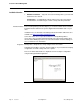
SECTION II: NETWORK SETUP Configuration via Enter the IP address or DNS name assigned to your adapter in the address bar of WEB your web browser. Navigate to the Network Settings page in the Administration area. BROWSER http:// http:// Once you enter new TCP/IP Settings in the browser view and press [Apply], you will see a change warning message: When DHCP is enabled, The new IP settings will take affect after you reboot the adapter.
SECTION II: NETWORK SETUP DHCP CLIENT AND NETWORK SETTINGS DHCP CLIENT ManageUPS ships with the DHCP client enabled. To disable the DHCP client and configure fixed IP settings, see the topic, Assign IP Settings on the next page. What happens if ManageUPS is unable to obtain settings via DHCP? If the client is unable to obtain an IP address from a DHCP server, ManageUPS will negotiate an IP address from the range reserved for Local networking (169.256.xxx.xxx).
SECTION II: NETWORK SETUP Current Network Settings Display the currently active TCP/IP settings of the adapter . DNS Hostname The DNS Hostname is retrieved from the DNS server on the network. Is there is no DNS entry for ManageUPS in the DNS server, the current IP address of the adapter will be displayed in the DNS Host Name field. The MAC address is a unique hardware identifier that is set in the ManageUPS adapter at the factory.
SECTION II: NETWORK SETUP TCP/IP Settings -- MENU ITEMS FOR STATIC IP SETTINGS IP Address Fixed IP address assigned to this adapter. Subnet Mask: Subnet Mask of the network that the UPS unit is on. Default Gateway: The local default gateway (IP address of the router). DNS Settings Primary DNS Server: Secondary DNS Server: Network Setup IP address of the primary DNS server. IP address of the secondary DNS server.
Network Setup 913-623 @Rev A User Guide, ManageUPSnet Section II, page 8
SECTION III: SETTING SERVICE OPTIONS Overview of Services Logging Service Pages 2-4 ManageUPS maintains event and data log files in non-volatile memory. Log files can be viewed via the WEB interface ⎯ or downloaded for import and analysis via other utilities. The default data log interval creates one entry every 10 minutes. This allows for approximately 26 days of history to be available for viewing. Log interval can be adjusted using the Log Controls menu.
SECTION III: SETTING SERVICE OPTIONS Logging Services UPS Events Log When you first access the Log viewing area, ManageUPS will load and display UPS events that have occurred in the last 24 hours. If there are no events to display, the display area will be blank.
SECTION III: SETTING SERVICE OPTIONS VOUT is AC voltage reported on the UPS output. VBATT is DC voltage reported at the battery. Some UPS report voltage at the string level. Other UPS report voltage at the cell level. In the example shown, 1837 is interpreted as 183.7 VDC. FREQ is the frequency of AC voltage on the input of the UPS. 600 is interpreted as 60.0 Hz. % LOAD is the UPS output load expressed as a % of UPS capacity as reported at the time the log entry is made..
SECTION III: SETTING SERVICE OPTIONS Network Time Resource The default entry for the network time resource is an internet timeserver - (requires internet access through NTP port 123). It is usually better practice to use a local time server within your network. ManageUPS will accept a local NTP server from the DHCP server automatically if it is offered.
SECTION III: SETTING SERVICE OPTIONS Event Messaging Services The messaging service sends messages on UPS status events via SNMP Trap, email or both. Email Settings SMTP Server: The IP address or DNS hostname of the SMTP host server that the adapter will use when sending email messages in response to an event. SMTP Settings SMTP Port: The port that the SMTP server is listening on (usually 25).
SECTION III: SETTING SERVICE OPTIONS Samples of e-mail message types Long From :ManageUPS27@Yournet.com Message Sent: 5 April 2004 Type To:TestR1@yournet.
SECTION III: SETTING SERVICE OPTIONS SNMP Traps The SNMP agent in ManageUPS conforms to the SNMP UPS MIB (RFC1628). The UPS MIB was originally circulated in SNMPv2 syntax. An SNMP v1 translation of RFC1628 MIB file is included on the ManageUPS CD and available from http://connectivity.chloridepower.com/products/manageups/ SNMP Trap Destinations Send Authentication Traps: Enables or disables the agent to send SNMP authentication traps.
SECTION III: SETTING SERVICE OPTIONS About SNMP UPS Alarm Table Entries WELL KNOWN ALARMS: (1-24) Content sent in Traps 3 and 4 include a numeric identity (upsAlarmId) of the specific alarm that has been added or removed from the table. The MIB defines 24 specific upsWellKnownAlarms. Value=1.3.6.1.2.1.33.1.6.3.x Where; x is the alarm identification number of the specific alarm entry.
SECTION III: SETTING SERVICE OPTIONS Network Shutdown Control Services Network Shutdown Controller Settings Remote Shutdown Enabled: Check to enable the Remote Shutdown Function. Restart Delay (applies to RCCMD only): The amount of time to wait after power has been restored to send the restart message to all IP addresses with a restart port greater than 0. This message will only be sent to those IP addresses that have received the Shutdown message.
SECTION III: SETTING SERVICE OPTIONS Group Settings Execute at [N] minutes remaining time: Send Shutdown Messages to all IP Addresses in the Group if the UPS is running on battery power and the amount of remaining time is estimated to be [N] minutes. Execute after [N]: Where N is the number of minutes on battery to wait Protocol: Select the protocol of the shutdown targets. If the shutdown target is running RCCMD listener module, select RCCMD.
Setting Service Options 913-623 @Rev A Section III, page 11
SECTION IV: ADMINISTRATIVE SETTINGS OVERVIEW OF ADMINISTRATION The Administration area contains menus and utilities for setting identity information, network parameters (covered in Section II), security and firmware maintenance. About ManageUPS The Product Identification area contains information that is useful when contacting your vendor for technical support. Ratings and Identity contains standard variables required in most SNMP applications.
SECTION IV: ADMINISTRATIVE SETTINGS PRODUCT IDENTIFICATION Name : Product Model Name. Firmware Version: Version of the ManageUPS services package that contains the device monitoring agent(s) along with related services and clients. Operating System Version: Version of the ManageUPS Operating System. Model Number: Adapter Model Number / Part Number. Serial Number: Adapter Serial Number is a 4 digit date code followed by the last 4 digits of the MAC ID.
SECTION IV: ADMINISTRATIVE SETTINGS Security Settings The security provided by ManageUPS is generally adequate for most applications that operate within a protected intranet environment. However, you should be aware that usernames, passwords and SNMP community names are transmitted over the network in plain text. Authentication and User Access control options are explained below. For further security, you may want to disable services that you are not using.
SECTION IV: ADMINISTRATIVE SETTINGS Server Settings Settings of the network servers hosted by the adapter. For greater security, use these controls to change port settings or disable any servers you are not using. Server: Name of the server/service on the adapter.. Enable: Enables/Disables server. If you disable the SNMP server -- all SNMP services will be disabled. The adapter will no longer accept SNMP get or set requests and will no longer send SNMP traps.
SECTION IV: ADMINISTRATIVE SETTINGS Utilities REBOOT / RESET UTILITIES The Utilities menus offer mechanisms for setting certain configuration parameters in the adapter and for managing various files in the adapter. Reboot the Adapter: This will cause the adapter to perform a reboot. This is required to cause system changes such as a change to the IP Address to take effect.
SECTION IV: ADMINISTRATIVE SETTINGS HARDWARE RESET There is a hardware RESET switch on the front panel of the adapter. The RESET, depending on the length it is depressed, performs one of three functions. 1. If the RESET switch is depressed for less than three seconds, it provides the same function as rebooting the adapter. 2. If the RESET switch is depressed anywhere from three to ten seconds, the USERNAME and PASSWORD revert back to the factory default. 3.
SECTION IV: ADMINISTRATIVE SETTINGS FILE MAINTENANCE ManageUPS allows for firmware, configuration and graphics files to be uploaded to the card over the network via TFTP or FTP. The File Transfer and Downloads utilities can be used to update adapter firmware or to simplify configuration of multiple adapters on your network. ManageUPS agent and services package. ManageUPS OS kernel snmp.conf Contains snmp trap and community settings System1.
SECTION IV: ADMINISTRATIVE SETTINGS USING TFTP To use the WEB interface for TFTP uploads you will need access to the TFTP server on your network. Place the files to be uploaded onto the TFTP server. Enter the address and file name (path) in the controls offered in the ManageUPS WEB interface: TFTP Host Name: IP address or hostname of the TFTP server containing the file to be transferred. File Name: The name of the file to be transferred.
Administrative Settings 913-623 @Rev A Section IV, page 9
SECTION V: DEVICE SETTINGS OVERVIEW OF DEVICE SETTINGS Status The Device menus provide a view of current status and access to dialogs for Diagnostics, Control and Configuration. Battery Status: States are Normal, Charging or Discharging. This value is returned as the object: UpsBatteryStatus in the UPS MIB - RFC1628. Battery Charge Remaining: Current percentage of the remaining total battery charge. This value is returned as the object upsBatteryChargeRemaining in the UPS MIB - RFC1628.
SECTION V: DEVICE SETTINGS Battery Capacity Designator: Typically the number of battery packs attached to the UPS. (NOT A MIB OBJECT) View the special help link for this parameter on the UPS Configuration page. UPS Up Time: The amount of time since the UPS was last started. (This value is returned as the sysUpTime object in MIB-2). Output Voltage The measured UPS output voltage. Output Source: The source of the UPS output power. Under normal conditions this will be Utility.
SECTION V: DEVICE SETTINGS Diagnostics Your UPS may not support all of the test options listed above. Your UPS may need to recharge its batteries after a battery test is complete. Your UPS may refuse to initiate a battery test if the battery is recovering from a previous test or if some other condition exists that would invalidate the results. Select a test by choosing the corresponding radio button. To start the test, click the button: "Perform Selected Diagnostic Function".
SECTION V: DEVICE SETTINGS Control Select one of the control actions by choosing the corresponding radio button. Click the "Perform Selected Action" button to start the action. NOTE: Your UPS may not support all of the options listed in this help dialog. Reset the Min/Max Measured Voltage Seen: A record of the Minimum and Maximum input line voltages are stored in your UPS, or in the ManageUPS UPS agent Mute the Audible Alarm: This action mutes the audible alarm for the duration of the current event.
SECTION V: DEVICE SETTINGS Configuration NOTE: Your UPS may not support all of the configuration options listed in this document. Temperature Threshold: The maximum internal UPS temperature allowed before triggering a UPS over temperature alarm. Overload Threshold: The maximum percent load allowed before triggering a UPS overload alarm.
SECTION V: DEVICE SETTINGS Authorized Autonomy: Triggers the UPS Low Battery alarm when the estimated minutes remaining value computed by the UPS reaches this value. (see Estimated Battery Life on the UPS Status page). This is the value a UPS administrator authorizes the UPS to use.
SECTION V: DEVICE SETTINGS About UPS This dialog area displays identity and nominal ratings of the UPS. For UPS that do not communicate identity and nominal ratings information, the form controls in the Ratings and Identity area allow the user to set this information in the ManageUPS adapter manually. The first time the web interface is accessed, ManageUPS may prompt you to confirm ups identity and ratings information that the UPS does not communicate to ManageUPS .
SECTION V: DEVICE SETTINGS Nominal Input Voltage: The line voltage that the UPS is designed to operate with. Nominal Input Frequency: The line frequency that the UPS is designed to operate with. Nominal Output Voltage: The nominal output voltage supplied by the UPS. Nominal Output Frequency: The nominal frequency that supplied by the UPS.
Device Settings 913-623 @Rev A Section V, page 9
SECTION VI: CONFIGURING MODBUS SERVICES P-SERIES ONLY Modbus TCPIP Communications ManageUPS Net Adapter P-Series supports both IP and Serial type Modbus communications. The default Modbus IP settings are shown in the WEB form below. Refer to the on-screen “help” files available from the WEB interface “?” in the Administration, Network Settings portion of the WEB menu. The Modbus Register map text file can be downloaded from the adapter.
Section VI: Configuring Modbus Services Troubleshooting Communications on Serial Networks The link on the Serial Settings dialog (previous page) will open a diagnostics dialog in the WEB interface to help troubleshoot or verify serial communications with the building monitoring system The screen below will report the activity seen by the adapter on the serial network. The UPS Alarm Test will cause the MODBUS RTU server to simulate alarm conditions.
SECTION VI: Configuring Modbus Services Physical RS485 Network Connection Use the RJ11 to Screw Terminal adapter provided. Connect 16AWG (or smaller) conductors from your RS485 network cable as shown below: Ground is Pin 1 D+ is connected to Pin 2 and Pin 4 D- is connected to Pin 3 and Pin 5 Pins 4 and 5 are also used in full duplex mode. Pin 6 is not used In half Duplex mode Pin(s) 2 & 4 and Pin(s) 3 & 5 are electrically connected to aid in the wiring of multiple devices on the Modbus network.
Section VI: Configuring Modbus Services Configuration for other To configure the adapter to use one of the other serial communications modes, Serial Communications you will need to change jumper settings on the adapter hardware. network Physical jumper locations are shown in the photo below.
SECTION VI: Configuring Modbus Services PIN Definitions for Other Communication Mode MODBUS Register Map The MODBUS Register MAP includes identity, measures and status information obtained from the UPS by the ManageUPS adapter. Some addresses are reserved as space for entering custom identification objects. This information will be retained in the adapter flash memory system, and presented in specific register addresses. Set this custom information using the WEB interface shown below.
Section VI: Configuring Modbus Services License Manager A License is needed to activate the Modbus feature on the ManageUPS Net Adapter P-Series. The license can be submitted in two ways. The first is in the factory where it is programmed prior to shipping. The second, by the customer through the html interface. It can be found in Administration >> License Manager. Insert the provided license key and press the Add License Key button.
SECTION VI: Configuring Modbus Services Troubleshooting There is a troubleshooting utility on the adapter that is accessible from the WEB interface. Use this utility to view what the adapter is receiving and sending on the RS485 network connection. See Modbus/Jbus configuration screen on bottom of page 1 of this section of the document.
SECTION VII: Configuring the ENVIRONMENT SENSOR P-Series Only ManageUPS Net Adapter P-Series Environment Sensor Environment Sensor Adhesive Backed Velcro Strip Blue Bus Cable 3m (15’) ManageUPS with Blue Bus port MIBs & Documentation CD Kit Components Hardware Specifications Environment Sensor Input power Single sensor powered from Blue Bus @ 7-24Vdc, < 0.36 watts Multiple sensors may require an auxiliary power supply.
Configuring the Environment Sensor Hardware Installation Single Sensor 1. Install the ManageUPS Net Adapter P-Series in your UPS. 2. Choose a location to mount the environment sensor within 3m (15’) of your UPS. 3. Use the adhesive-backed Velcro Strip to attach the Sensor to the mounting location. 4. Connect the Blue Bus cable between the Blue Bus port in the ManageUPS Net Adapter P-Series and a Blue Bus port on the sensor. (Connect the filtered end of the cable to the ManageUPS Net Adapter P-Series.
Configuring the Environment Sensor BROWSER The “Environment” menu provides a view of current status and quick links to Environment Logs. OVERVIEW OF DEVICE SETTINGS Environment Logs can also be reached from the dropdown list on “Logging” menu. INTERFACE: Configuration menus are accessed from the link on the Environment Status page. Status View Environment: Measures of Temperature and Relative Humidity are displayed. These values are returned as MIB objects in the Chloride Environment Sensor MIB.
Configuring the Environment Sensor Configure Sensor Settings The configure sensors page displays the current status at the top page – and provides three sections for configuring : o Environment Sensor Settings o Input Device Settings o Output Device Settings Use the scroll bar at right to reveal the sections at the lower part of the page. The APPLY button in each section enters the settings for that section.
Configuring the Environment Sensor Environment Sensor Settings – Help Detail Entries Event Severity The severity level of each of the conditions described above is determined using the Event Severity setting. If this setting is Disabled then no condition will be generated and the status will always be Normal. Sensor Name: A user configurable name given to the sensor.
Configuring the Environment Sensor Input Device Settings – Help Detail Entries Name (1-3): A user configurable name given to the input device. (These values are the inputName1, inputName2, inputName3 objects in the Chloride Power Environment Sensor MIB) Normal State (1-3) The normal state of the input contact. When the input contact is not in this state the input fault condition is generated..
Configuring the Environment Sensor Output Relay Settings – Help Detail Entries Name: A user configurable name given to the output relay. (These values are the ouputName objects in the Chloride Power Environment Sensor MIB) URL: A url associated with this device. Must be in the format 'http://hostname'. When this value is set the output name becomes a link on the environment status page.
Configuring the Environment Sensor CHLORIDE POWER ENVIRONMENT SENSOR MIB ManageUPS Net Adapter P-Series with Environment Sensor option supports three SNMP MIBs: The UPS MIB is an SNMPv1 translation of RFC1628 (1.3.6.1.2.1.33) The environment sensor MIB is a private enterprise MIB . (1.3.6.1.4.1.1364.10) The sensor MIB is organized in tables of object values, alarms and traps. Each entry shown on the WEB interface is represented as an object in the sensorTable sensorEntries.
Configuring the Environment Sensor Example of environment Sensor MIB sensorTable sensorEntries Single Sensor Two Sensors Object Name Object Value Object Name Object Value numSensors.0 1 numSensors.0 2 name.1 status.1 address.1 temperature.1 tempStatus.1 tempHiSeverity.1 tempLoSeverity.1 tempHiThreshold.1 tempLoThreshold.1 humidity.1 Rack 1 Warning 32 21 Normal Warning informational 43 20 32 name.1 Rack 1 name.2 My Sensor status.1 warning status.2 Normal Address.
Environment Sensor 913-623 @Rev A Section VII, page 10
APPENDIX A: CONFIGURING MANAGEUPS VIA SERIAL PORT You will need an ASCII terminal or terminal emulation program on your PC workstation. ASCII Terminal HyperTerminal is a standard terminal emulation program offered with Windows. See Terminal Settings on the following page for instructions on how to set up Hyper Terminal to work with ManageUPS.
APPENDIX A: CONFIGURING MANAGEUPS VIA SERIAL PORT (CONT'D) BPS = 1200, 2400 or 9600 (Depends on UPS model family.
APPENDIX B: ALARM DETAIL - UPS CONDITIONS THAT TRIGGER MANAGEUPS MESSAGING SNMP Alarm ID 6 7 SNMP MIB OID Ref: Log Entry & Condition Email Subject upsAlarmInputBad upsAlarmOutputBad Probable Cause Input power is out of limits or not present. SNMP Trap only An output condition is out of tolerance. SEVERE! Condition Codes 1 upsAlarmBatteryBad Module Battery Needs Replacing UPS Battery needs replacing. 4 upsAlarmDepletedBattery Module Depleted Battery Run time is just about zero.
APPENDIX B: ALARM DETAIL - UPS CONDITIONS THAT TRIGGER MANAGEUPS MESSAGING SNMP Alarm ID SNMP MIB OID Ref: Log Entry & Condition Email Subject Probable Cause Warning! Condition Codes 2 upsAlarmOnBattery Module On Battery UPS is running on battery power. 3 upsAlarmLowBattery Module Low Battery Condition Run time left is less than configured low battery alarm value. 9 upsAlarmOnBypass Module On Bypass The bypass is engaged by the UPS.
APPENDIX B: ALARM DETAIL - UPS CONDITIONS THAT TRIGGER MANAGEUPS MESSAGING System Log Entries Warning LogEntry & Condition Email Subject Probable Cause Failed To Synchronize System Clock With NTP Server The adapter could not reach the identified NTP server Communication Established The adapter established Communications with the UPS MopUPS Service Started The Adapter's device monitoring service has started successfully MopNSA remote shutdown: failed to authenticate to : Informa
APPENDIX C: POWER COMPATIBILITY TABLE FOR MANAGEUPS BLUE BUS ACCESSORIES Number of Environment Sensors that can be powered by ManageUPS Blue Bus without auxiliary power supplied to the sensor. Note: Please contact your local distributor if your UPS is not listed here.
APPENDIX C: POWER COMPATIBILITY TABLE FOR MANAGEUPS BLUE BUS ACCESSORIES Masterguard Brand UPS Models UPS Family Series A Series E ManageUPS Net Adapter (230V) ** 6kVA 0 10-20kVA 2 Series Ei (6/10kVA) 8 Ci / Siii (2-slot) 8* ManageUPS Net Adapter w/ External Chassis 8 * Value assumes ManageUPS is the only accessory in the multi-slot. If a LIFE modem or other accessory is also installed in the multi-slot accessory bay, subtract 3.
APPENDIX C: POWER COMPATIBILITY TABLE FOR MANAGEUPS BLUE BUS ACCESSORIES ONEAC Brand UPS Models UPS Family ManageUPS Net Adapter ONe + Sinergy A Sinergy E ManageUPS Net Adapter w/ External Chassis NA (120V) 3 6kVA 0 10-20kVA 2 Sinergy II 5 ON v96 .6 – 2.2 kVA 3 ON v96 3-5kVA 3 ON UM .7-2kVA 5 8 * Value assumes ManageUPS is the only accessory in the multi-slot. If a LIFE modem or other accessory is also installed in the multi-slot accessory bay, subtract 3.
APPENDIX D: MANAGEUPS TECHNICAL SPECIFICATIONS Specifications and Features ManageUPS P-Series Network Interface 10/100 Base-T Ethernet — Ethernet Class 1 (DIX) packet format 802.
APPENDIX E: MANAGEUPS MODBUS REGISTER MAP Information available via Modbus Function Code 03 - Read Holding Registers All points are unsigned integers Default MODBUS Offset is 1 (configurable via WEB interface) 90Net CP3020 CP3150 EDP70, 70L, 90 (Single) Designation 80Net (Default Modbus point) 000h (1) 70Net Relative Address Linear Plus Information Supported by UPS Model √ √ √ √ √ √ √ √ √ √ √ √ √ √ √ √ √ √ √ √ √ √ √ √ √ √ √ √ √ √ √ √ √ √ √ √ √ √ √ √ √ √
APPENDIX E: MODBUS REGISTER MAP Information available via Modbus Function Code 03 - Read Holding Registers All points are unsigned integers Default MODBUS Offset is 1 (configurable via WEB interface) 90Net CP3020 CP3150 EDP70, 70L, 90 (Single) Designation 13 14 15 16 17 80Net (Default Modbus point) 00Eh (15) 00Fh (16) 010h (17) 011h (18) 012h (19) 70Net Relative Address Linear Plus Information Supported by UPS Model √ √ √ √ √ √ √ Comment reserved reserved reserved reserved reserved up
APPENDIX E: MODBUS REGISTER MAP Information available via Modbus Function Code 03 - Read Holding Registers All points are unsigned integers Default MODBUS Offset is 1 (configurable via WEB interface) Designation EDP70, 70L, 90 (Single) CP3150 CP3020 90Net (Default Modbus point) 80Net Linear Plus Relative Address 70Net Information Supported by UPS Model Comment 028h (41) 10 upsInputRealPower L1 [0,1kW] √ √ 029h (42) 11 upsInputRealPower L2 [0,1kW] √ √ 02Ah (43) 12 upsInputRealPow
APPENDIX E: MODBUS REGISTER MAP Information available via Modbus Function Code 03 - Read Holding Registers All points are unsigned integers Default MODBUS Offset is 1 (configurable via WEB interface) Information Supported by UPS Model 040h (65) 041h (66) 042h (67) 043h (68) 044h (69) 16 17 18 19 20 EDP70, 70L, 90 (Single) 15 CP3150 03Fh (64) CP3020 14 90Net 03Eh (63) 80Net 13 70Net (Default Modbus point) 03Dh (62) Linear Plus Relative Address √ √ √ √ √ √ √ [%] √ √ √ √ √ √ [%
APPENDIX E: MODBUS REGISTER MAP Information available via Modbus Function Code 03 - Read Holding Registers All points are unsigned integers Default MODBUS Offset is 1 (configurable via WEB interface) 90Net CP3020 CP3150 EDP70, 70L, 90 (Single) Designation 80Net (Default Modbus point) 70Net Relative Address Linear Plus Information Supported by UPS Model √ √ √ √ √ √ √ Comment upsAlarm 1 056h (87) bit 0 2 056h bit 1 3 056h bit 2 4 056h bit 3 upsAlarmsPresent Nb.
APPENDIX E: MODBUS REGISTER MAP Information available via Modbus Function Code 03 - Read Holding Registers All points are unsigned integers Default MODBUS Offset is 1 (configurable via WEB interface) CP3150 √ √ √ √ √ √ √ √ √ √ √ √ √ √ √ √ √ √ √ √ √ √ √ √ √ √ √ √ √ √ √ √ √ upsAlarmFanFailure √ 34 35 36 37 38 39 40 41 42 43 44 45 46 47 upsAlarmFuseFailure upsAlarmGeneralFault upsAlarmDiagnosticTestFailed upsAlarmCommunicationsLost upsAlarmAwaitingPower upsAlarmShutdownPe
APPENDIX E: MODBUS REGISTER MAP Information available via Modbus Function Code 03 - Read Holding Registers All points are unsigned integers Default MODBUS Offset is 1 (configurable via WEB interface) CP3150 √ √ √ √ √ 3√ √ √ √ √ √ √ √ √ √ √ √ √ √ √ EDP70, 70L, 90 (Single) CP3020 Designation 90Net (Default Modbus point) 80Net Linear Plus Relative Address 70Net Information Supported by UPS Model Comment (0) Rectifier off (1) Rectifier turning on (2) Rectifier on (3) Rectifier