400 Range Dialer Installation Manual Version 1.
The information contained is supplied without liability for any errors or omissions. No part may be reproduced or used except as authorised by contract or other written permission. The copyright and foregoing restriction on reproduction and use extend to all media in which the information may be embedded.
Contents 1. Introduction ...................................................................................................... 1 1.1. About this manual… .............................................................................. 1 1.2. Overview ................................................................................................ 1 1.3. System specifications ............................................................................ 2 2. Before you start… .................................
ii Iris Touch 400 Range Dialer Installation Manual
1. Introduction 1.1. About this manual… This manual is designed to help you, the Installer, with the installation process for the IRIS Touch alarm dialer. We recommend that you read through this manual, in its entirety, before you visit the customer’s site and begin the installation. 1.2.
1.3.
2. Before you start… 2.1. Package contents In this package you should have the following components: • • • Main dialer PCB with four self-adhesive feet • • • • Antenna for GSM/GPRS. (GSM / Ethernet & GPRS only). 2.2. Power cable (black) for connection to DC supply. Ethernet cable (cream) for connection to IP network. (Ethernet / Ethernet & GPRS only). Dialer cable (grey) for connection to dialer output of alarm panel. Sense resistor (18K ohm) for alarm dialer cable fault/tamper detection.
3. Alarm dialer interface IRIS dialers carry alarm signals from the alarm panel over IP completely transparently so when they arrive at the Monitoring Centre it is as though they had come over a traditional PSTN connection. IRIS dialers support SIA (Levels 1 to 3), Contact ID, Scancom (Fast Format) and Robofon protocols, one of which virtually all alarm panels will support. Apart from the following, no reconfiguration of the alarm panel is required for use with IRIS dialers: 1.
4. Installing the IRIS Touch Dialer Use the following procedure to install the IRIS Touch Dialer. Note: For installations using PIN alarm inputs see the PIN alarms section for additional information and for wiring to relay outputs see the Relay outputs section. Do not apply power to the dialer until indicated. 1.
6. Plug in the external cables • Plug the dialer cable into the alarm panel dialer. If the alarm panel has screw connections, cut the connector off the cable and strip the cable using the 2 inner wires. Polarity is not important. • Plug the Ethernet cable into the local IP router or socket that has been allocated for the IP connection. 7. Plug in the sense resistors Fit the 18K sense resistor in parallel with the dialer output of the alarm panel, at the alarm panel end of the cable.
5. Configuring the IRIS Touch Dialer The majority of configurations can be carried out via the touch screen interface display on the IRIS dialer. For more complex systems, for example where the data port is used, additional configuration is available via the USB connector using a laptop / PC and IRIS dialer configuration software (available via the Chiron website).
6. Post installation If a fault should develop, then the LED light on the top of the unit will start flashing and the display will show a system fault message. This message can be touched to gain access to more information. 7. PIN alarms The IRIS Touch series have PIN inputs [7] that can be used to generate alarm messages. These can be: • • Text messages via SMS (GSM / Ethernet & GPRS only). • Fast Format alarm messages over IP to the Monitoring Centre (Ethernet / Ethernet & GPRS only).
7.1. Installation Each PIN input is designed to be connected in a loop via an open/close contact source from an alarm panel, or other device, to a reference ground PIN [8] available on the IRIS dialer, as shown below: Reference ground Pin inputs 1 4 Opening the contact (i.e. loop is open circuit) generates an alarm signal. Closing the contact generates the equivalent restore signal.
7.2.
9. Troubleshooting Problem Resolution No screen display when IRIS dialer is connected to the power. Check that there is power to the system and that the wiring is the correct polarity. A fault develops and is indicated by the LED on the PCB flashing. Touch the display and the instructions will guide you through identification of the problem. Go to the Installers menu and select Test to use the integrated test function.
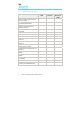
Appendix A – Settings menu Setting Purpose Network Interfaces Selects which network interfaces are going to be used (i.e. Ethernet and/or Ethernet/GPRS). Stops dialer reporting trouble on interfaces not being used. Account Number/Name The IRIS account number/name, as allocated by the Monitoring Centre. Monitoring Centre IP Address IP address of the receiver at the Monitoring Centre. Dialer IP Address IP address of the dialer, i.e. either automatic (DHCP) or fixed.
Appendix B – Installation photo [8] [7] [9] [3] [2] [1] [4] [6] [5] Iris Touch 400 Range Dialer Installation Manual 13
Appendix C – Specification Alarm Dialer Interface Two wire interface via RJ11 socket 40V feed at 12mA Ringing voltage 40V P-P to REN4 for incoming calls Off hook detection with dial-tone presented to alarm dialer DTMF tone recognition for dialing outgoing calls and alarm signaling Ethernet Interface 10Mbps and 100Mbps (10/100BaseT) with auto-negotiation UTP with standard RJ45 socket for CAT-5 cabling Dynamic IP addressing (DHCP) or fixed GSM/GPRS Interface Dual band GSM 900 MHz and DCS 1800 MHz MMCX socket
Conformance The IRIS range of alarm dialers comply with the following European Directives: • • • 1999/5/EC (Radio & Telecoms Terminal Equipment Directive). 72/23/EEC (Low Voltage Directive). 89/336/EEC (Electromagnetic Compatibility Directive as amended by 92/31/EEC).