Chiron Technology IRIS 8xx Series Alarm over IP Dialler Installation and User Guide Chiron Technology Wyvols Court Swallowfield Reading UK Tel: E-mail: +44 (0)118 988 0228 sales@chiron.uk.com support@chiron.uk.com Chiron Technology Ltd 2004 Version 0.7 2/9/05 The information contained is supplied without liability for any errors or omissions. No part may be reproduced or used except as authorised by contract or other written permission.
Table of Contents 1 OVERVIEW 5 2 PRODUCT INVENTORY 6 3 INTERFACES AND INDICATORS 7 3.1 IRIS 800 3.1.1 PCB Unit – Front Panel Indicators 3.1.2 PCB Unit – Rear Panel Connectors 3.1.3 Cased Unit – Front Panel Indicators 3.1.4 Cased Unit – Rear Panel Indicators 7 7 7 7 7 3.2 IRIS 820 3.2.1 PCB Unit – Front Panel Indicators 3.2.2 PCB Unit – Rear Panel Connectors 3.2.3 Cased Unit – Front Panel Indicators 3.2.4 Cased Unit – Rear Panel Connectors 8 8 8 8 8 3.3 IRIS 850 3.3.
6.2 Physical Installation 17 6.3 Checking and Network Connection 17 6.4 Polling Configuration 18 6.5 Alarm Transmission 18 7 INSTALLATION – BACKUP TRANSMISSION OVER GSM 19 7.1 Preparation Prior to Installation 19 7.2 Physical Installation and Checking Network Connection 19 7.3 Alarm Transmission 19 8 8.1 ADVANCED INSTALLATION - DATA CALLS Installation 20 20 8.2 Configuration 8.2.1 General 8.2.2 Calls over ISDN using V.120 Rate Adaption 8.2.3 Calls over Ethernet using TCP/IP 8.2.
14 SPECIFICATION 29 14.1 Feature comparison 29 14.2 Polling over IP 30 14.3 Alarms over IP 30 14.4 Alarm and Polling Security 30 14.5 Alarm System Upload/Download 30 14.6 Alarm Interface 30 14.7 Ethernet Interface 31 14.8 ISDN Interface 31 14.9 PSTN Interface 31 14.10 GSM/GPRS Interface 31 14.11 SMS Messaging 31 14.12 Data Interface 32 14.13 Pin Inputs 32 14.14 Relay Outputs 32 14.15 LED Status Indicators 32 14.
1 Overview The Chiron IRIS Alarm over IP Dialler range offers a unique way to connect any standard alarm dialler over an IP network, with backup over traditional PSTN or ISDN dial-up networks and/or GSM/GPRS wireless networks if required. An integral polling mechanism is included in all products to provide constant monitoring of the communications paths so that any problems are reported to the ARC. Advanced features such as data calls and SMS messaging are also offered.
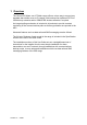
2 Product Inventory The accessories included with each IRIS unit are as follows: Main IRIS unit Plug top mains power supply Power cable Ethernet cable (cream) Dialler cable (grey) ISDN cable (black) PSTN cable (grey) Velcro mounting Antenna CD IRIS 800 (PCB) IRIS 800 (Cased) IRIS 820 (PCB) IRIS 820 (Cased) IRIS 850 (PCB) • • • • • • • • • • • • • • • • • • • • • • • • • • • • • • • • • Optional • When using the Local Configuration Console, a standard 9-way modem serial cable is required
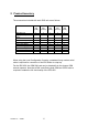
3 Interfaces and Indicators The interface and indicators on each unit are shown below. Please see the Installation sections for more details on how these are used. 3.1 IRIS 800 Note – for the IRIS 800 the PCB version is narrower than the cased version. 3.1.1 PCB Unit – Front Panel Indicators PWR DIAL ETH POLL ETH 3.1.2 PCB Unit – Rear Panel Connectors DIAL V24 3.1.3 Cased Unit – Front Panel Indicators IRIS 800 DIAL ETH Alarm Adapter POLL RD SD 3.1.
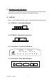
3.2 IRIS 820 3.2.1 PCB Unit – Front Panel Indicators PSTN DIAL ETH POLL RD SD TR ISDN 3.2.2 PCB Unit – Rear Panel Connectors PWR PSTN V24 DIAL ETH ISDN 3.2.3 Cased Unit – Front Panel Indicators IRIS 820 PSTN DIAL ETH Alarm Adapter POLL RD SD TR ISDN 3.2.4 Cased Unit – Rear Panel Connectors PWR Version 0.
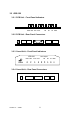
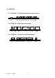
3.3 IRIS 850 3.3.1 PCB Unit – Front Panel Indicators and Connector ANT PSTN DIAL ETH POLL GSM RD SD TR ISDN 3.3.2 PCB Unit – Rear Panel Connectors PWR PSTN DIAL V24 ETH ISDN 3.3.3 PCB Unit – Pin Inputs and Relay Outputs OUT A & B Version 0.
The function of each indicator is shown in the table below. Name Function PSTN DIAL ETH POLL GSM RD SD TR ISDN PSTN network connection status.
4 Installation – Alarm Transmission and Polling over IP 4.1 Preparation Prior to Installation 1. Check that the ARC to which connection is to be made supports Chiron’s IRIS Alarm over IP system. 2. The IP address of the Polling Engine/Receiver at the ARC is required – this will be a twelve digit number. Note – IP addresses are often provided as four numbers separated by the “.” character, e.g. 192.168.3.34.
5. The Dialler has the facility to monitor the connection to the alarm dialler so that it can detect disconnection and report this to the ARC. If this facility is required, connect an 18K ohm sense resistor across the 2-wire analogue interface on the alarm dialler. Note – for this feature to work correctly it is essential that this resistor is connected at the alarm dialler end of the cable, not the Dialler end. 6.
4.4 Polling Configuration 1. To start up polling from the IRIS Dialler to the ARC, the Dialler must be loaded with the IP address of the ARC and the account number of the dialler, both of which can be loaded into the IRIS Dialler from the dialler. 2. Make sure the alarm dialler is set up with its account number. Set the IP address of the ARC (i.e. twelve digits) into the ARC telephone number field in the alarm dialler configuration. 3. Trigger the dialler to transmit an alarm.
3. If a backup or second path is required, the twelve digit IP address of the second receiver should be programmed into the second ARC telephone number field of the dialler. 4. Having set up the alarm transmission as required, it is strongly recommended that all routes are tested by generating alarm signals. During alarm call testing a standard PSTN line monitor can be used to listen in to the alarm communications including ‘handshake’ and ‘kiss-off’ tones to confirm correct operation. Version 0.
5 Installation – Backup Transmission over PSTN or ISDN PSTN or ISDN can be used as a backup for alarm transmission, providing an alternative route to the ARC. Polling does not operate over ISDN or PSTN as this would incur high call charges. The procedures described in this section are in addition to those described in the previous installation section. 5.1 Preparation Prior to Installation 1.
only ever starts with a “0”, “1” or “2’. The IRIS Dialler discards the “9” and dials the call using the subsequent digits. 2. The IRIS Dialler will call over ISDN if this is connected or over PSTN if not. The installer therefore detects the route required (PSTN or ISDN) just by plugging in the appropriate cable. 3. Most alarm diallers allow two ARC numbers to be programmed which can be used in primary/backup mode or for dual path signalling.
6 Installation – Backup Polling/Transmission over GPRS GPRS can be used as a backup for polling and alarm transmission over IP providing an alternative route to the Polling Engine/Receiver at the ARC. Alarm transmission calls are routed to the same ARC receiver as would be used with ISDN or PSTN. The procedures described in this section are in addition to those described in the previous installation sections. 6.1 Preparation Prior to Installation 1.
• • • SIM card not fitted (or not valid) Antenna not connected Signal strength too low 6.4 Polling Configuration 1. Providing polling over IP has been configured as described in the section above, the IRIS Dialler will automatically poll over GPRS to the same ARC IP address if it cannot complete a poll over IP. 2. The POLL indicator indicates poll success as with polling over IP. 6.5 Alarm Transmission 1.
7 Installation – Backup Transmission over GSM GSM can be used as a backup for alarm transmission, providing an alternative route to the ARC. Polling does not operate over GSM as this would incur high call charges. The procedures described in this section are in addition to those described in the previous installation section. 7.1 Preparation Prior to Installation 1. A SIM card supporting GSM voice calls is required. 7.2 Physical Installation and Checking Network Connection 1.
8 Advanced Installation - Data Calls The Dialler supports data transmission either over ISDN (as a standard ISDN Terminal Dialler) or over IP, for applications such as Video Surveillance. This function is separate from the alarm-transmission and SMS features and can be used simultaneously. 8.1 Installation 1. Ensure that the Dialler is connected to the communications network required, either ISDN, Ethernet or GPRS, as described in the Installation section above. 2. Connect the terminal equipment (e.g.
8.2 Configuration Configuration required for data calls can normally be done by the attached equipment using Hayes commands. Depending on the network being used, the commands are as follows: 8.2.1 General Command Function &F S0=1 S0=0 Sets defaults for data port Sets auto-answer on (if required) Sets auto-answer off (if not required) 8.2.2 Calls over ISDN using V.120 Rate Adaption Command Function %A2=2 Selects V.
8.2.4 Calls over GPRS using TCP/IP Command Function %A2=19 %I6=abcde Selects TCP/IP calls over GPRS Sets Dialler TCP port number to abcde (must be five digits from) Sets called TCP port number to fghij (must be five digits) %I7=fghij Dialling is as described in the section above. Version 0.
9 Advanced Installation - SMS Messaging SMS support on the IRIS Dialler range provides eight pin inputs that can be used to generate SMS messages and four relay outputs that can be switched on and off by incoming SMS messages. These features can be used for control and monitoring applications, even in locations where no telephone line is present, for example: • • • Control of door lock to allow a caller to enter. Switching heating on and off. Alert on refrigerator failure. 9.1 Installation 1.
4. It is recommended that inputs and outputs selected are tested by the installer while on site. Version 0.
10 Alarm Panel Upload and Download Management calls using a standard modem and the alarm panel’s standard management software for upload/download are supported by the IRIS Dialler. Calls can be originated by the dialler and routed via the Dialler over IP or over an ISDN or PSTN dial up link. Alternatively calls can be originated from the management centre and routed to the dialler via IP, ISDN or PSTN. Calls over IP use Voice over IP (VOIP) technology to transport the modem signals over the IP network.
11 Local Configuration Console 11.1 Installation of the Local Configuration Console Software The Chiron IRIS Dialler configuration software is provided on the CD that is supplied with the unit. To install the software on a PC or Laptop use the following procedure: • Place the CD in the CD ROM drive of the PC or lap-top. • Click the ‘Start’ button and select ‘Run…’. • Click the ‘Browse’ button and open the CD ROM drive (normally D:).
12 Local Configuration with a Telephone Handset Some of the configurations that may be required by the Dialler can be entered by using a standard telephone connected to the ‘DIAL’ port in place of the alarm dialler. Configurations are entered using ‘*’ commands, as follows: 12.1 Dialler Default To set default configuration use: *9**1234567890#. 12.2 IP Address By default the Dialler will automatically negotiate its IP address with the IP network.
13 Troubleshooting If problems are experienced, the following guide will be off assistance. Please also refer back to the installation instructions above and check that the correct procedures have been followed. Symptom Possible Causes All LEDs off. No power applied. Check power connection and polarity. On the cable provided, the white stripe indicates negative. No 50V signal applied to dialler. Check cabling between dialler 2 wire connection and DIAL port on Dialler. Dialler reports a Telecom fault.
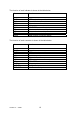
14 Specification 14.1 Feature comparison The different features of the models in the IRIS 8xx range are shown in the table below.
14.2 Polling over IP Configurable polling interval (10s to 40mins) set by ARC IP Polling Engine address and account number automatically picked up from alarm dialler Alternative primary and backup numbers can be loaded by ARC Status of all communications links reported to ARC Automatic backup over GPRS Uses TCP connection outbound from IRIS Dialler to port number 52737 at ARC 14.
14.7 Ethernet Interface 10Mbps and 100Mbps (10/100BaseT) with auto-negotiation UTP with standard RJ45 socket for CAT-5 cabling Auto-sensing of Ethernet 802.2, DIX and SNAP formats ARP (Address Resolution Protocol) support Dynamic IP addressing (DHCP) 14.8 ISDN Interface Basic Rate 2B+D, Q.921, Q.931 ‘S’ bus compatible Conforms to European ETSI standard TBR 3 RJ45 socket with cable provided Point-Point and Point-Multipoint operation Multiple Subscriber Numbering support Data calls using V.
14.12 Data Interface Asynchronous 9 pin RS232 interface Autobauding to 115.2 Kbps Hayes AT compatible RTS/CTS flow control 14.13 Pin Inputs Maximum input voltage range Input ‘low’ threshold Input ‘high’ threshold Input pull-up impedance 0V to +24V < 2V > 3V Internal 10K to 5V supply 14.14 Relay Outputs Maximum operating voltage Maximum current rating 24V 1A 14.
15 Conformance and Safety 15.1 Conformance The IRIS Diallers comply with the following European Directives: 1999/5/EC 72/23/EEC 89/336/EEC (Radio & Telecoms Terminal Equipment Directive) (Low Voltage Directive) (Electromagnetic Compatibility Directive as amended by 92/31/EEC) 15.
If PSTN or ISDN are used as a backup then the system complies with Performance Criteria ATS 4. The ARC should enable monitoring of this connection. The IRIS Diallers have been assessed and certified against these standards by Telefication B.V. 15.3 Safety Care should be taken that when interconnecting telecommunications equipment that only like interfaces are interconnected to avoid safety hazards.