Chiron Technology IRIS Management Suite Technical Guide for the User Chiron Technology Wyvols Court Swallowfield Reading UK Tel: E-mail: +44 (0)118 988 0228 sales@chiron.uk.com support@chiron.uk.com Chiron Technology Ltd 2007 Version 1.7C 4/11/07 The information contained is supplied without liability for any errors or omissions. No part may be reproduced or used except as authorised by contract or other written permission.
Contents 1 2 3 4 Document Change History ........................................................................ 3 Introduction to the IRIS Management Suite .............................................. 4 System Sizing ............................................................................................ 5 Getting Started .......................................................................................... 7 4.1 Installation .....................................................................
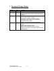
1 Document Change History Version Date Changes 1.7C 4/11/07 1.7B 14/7/06 1.7A 31/1/06 Added section to give more details about communications link monitoring and poll overdue handling. Guide to system menus included. Guide to sizing IP link to diallers. Description of operation of dialler remote management and remote voip connection for upload/download of panel. Added IP port numbers used by IRIS system. Added description on new Polling Engine Group function. Added ‘Getting Started’ section.
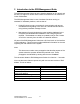
2 Introduction to the IRIS Management Suite The IRIS Management Suite acts as the interface between an IP network and the ARC for support of remote Alarm Panels connected to the IP network via Chiron IRIS diallers. The IRIS Management Suite is a set of software functions running on standard PC hardware platforms, and consists of: • Polling Engines (as many as required), communicating with remote IRIS diallers and signalling to the ARC via a standard serial interface using industry standard message formats.
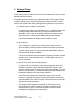
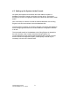
3 System Sizing There are a number of factors that should be considered when sizing an IRIS Management Suite system. The details below are based on the assumption that the main system activity is diallers polling into the IRIS Polling Engine and that the amount of alarm traffic (even at peak levels during opening/closing periods) is not significant. 1) Polling Engine PC platform performance. In practice any medium spec PC platform (e.g. 2.
250 IP link bandwidth (Kbits per sec) 200 150 20s polling 60s polling 180s polling 600s polling 100 50 0 50 100 200 500 1000 Number of diallers Iris Management Suite Technical Guide V1.
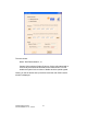
4 Getting Started Setting up the IRIS Management Suite is very easy. All software required is contained on a single CD and is installed in the normal way by running the setup.exe applications on the CD. 4.1 Installation The software that should be installed is the IRIS Console (single instance) and the IRIS Polling Engine (on as main hardware platforms as required).
The user should: Select “IRIS Demonstration”, or Contact Chiron with the Product ID shown. Chiron will respond with a Licence Key that should be entered into the fields shown. This will enable the system for the number of diallers and time period agreed. Clicking on the OK button sets up the licence and the main IRIS Console window is displayed. Iris Management Suite Technical Guide V1.
4.3 Setting up the System via the Console All system parameters and information about the diallers are held in a database on the IRIS Console, so this has to be set up first. This is done through the Console’s configuration windows and these are described in detail below. Part of this setup is to tell the Console the network addresses of the Polling Engines, so that it knows where to send the database files.
5 Console and Polling Engine Windows This section gives an overview of the functionality of each of the windows used for viewing system operation and setting up the system and dialler database. Subsequent sections give more detail on the operation of specific features of the IRIS system. In general the Console and the Polling Engines use the same window format.
5.1 Main Windows The main windows of the Console and the Poling Engines are as shown below: Console: 4 1 5 3 Polling Engine: 4 1 5 2 3 6 7 Iris Management Suite Technical Guide V1.
Item Purpose Description 1 Dialler database display Shows all diallers in database for group selected in Item 4. Double click on this area to enter dialler configuration window. 2 ARC messages display 3 Monitor display 4 Dialler display filter selection 5 6 7 Access system configuration windows Show connections status Clears adjacent display Iris Management Suite Technical Guide V1.
5.2 Configuration Selection System, Console and Polling Engine configuration windows are accessed by clicking on the Edit Config button in the main window. This brings up the Configuration Selection window shown below. 1 2 3 Item Purpose Description 1 Select which device to configure Shows which application is being accessed Close options Click on appropriate button to select what is to be configured. The indicator is highlighted for the application that the user is currently accessing.
5.3 System and Console Configuration 1 4 2 5 3 6 Item Purpose Description 1 Determines what is displayed in Console Monitor window Pairs Polling Engines ‘All’ selects everything. ‘Normal’ prevents routine events being displayed. 2 3 4 5 6 Set poll overdue margins Open Licence window Sets up dialler link fail detection Exit options Iris Management Suite Technical Guide V1.
5.4 Polling Engine Configuration 1 2 9 3 4 10 5 11 6 7 8 12 Item Purpose Description 1 Polling Engine name Free text field. 2 Sets Polling Engine Group number within which this Polling Engine sits Polling Engine network location See section below for description of Group function.
8 9 Sets the account number used for reporting system events Dialler link IP address System events, which are not dialler specific, such as dialler link fail are reported to the ARC on this account number. This is the IP address that will be sent to any dialler that is told to use this Polling Engine as its main or backup. If the Polling Engine sits behind an address translating gateway or firewall, this must be the ‘public’ IP address on the other side of the gateway.
5.5 Dialler Configuration The Dialler Configuration window is accessed by double clicking on the dialler database display area on the main window. Information relating to the particular dialler on which the pointer sits will be displayed. This window is used to add a new dialler, prior to installation, or to subsequently modify a dialler set up. It is important that the dialler is setup prior to installation or the installation process will not complete successfully.
The Last Valid Key field shows the actual key in use by the dialler. Note this field is only refreshed when this window is opened. 4 5 Set main and backup Polling Engines for this dialler Sets polling interval 6 Automatically adds more database entries 7 8 Save or delete dialler Free text area for description of dialler Dialler remote access functions 9 10 Sets which dialler interfaces are monitored so that status changes are reported to ARC as Trouble/Restore.
6 Grouping Polling Engines In some cases it is desirable to be able to duplicate dialler account numbers so that more than one dialler can use the same account number and yet each can be uniquely identified by the IRIS System. This could be, for example: • For very large systems where the number of diallers installed is greater than the number of account codes available. • To support an existing estate of diallers where it is convenient to leave the existing account numbers unchanged.
MAIN POLLING ENGINE GROUP 0 IP xxx.yyy.zzz.1 BACKUP POLLING ENGINE GROUP 0 IP aaa.bbb.ccc.1 MAIN POLLING ENGINE GROUP 1 IP xxx.yyy.zzz.2 IP NETWORK ACCOUNT NUMBER 1973 SET TO POLL TO xxx.yyy.zzz.1 Example of Polling Engine Grouping Iris Management Suite Technical Guide V1.7C 4/11/07 20 ACCOUNT NUMBER 1973 SET TO POLL TO aaa.bbb.ccc.1 BACKUP POLLING ENGINE GROUP 1 IP aaa.bbb.ccc.
7 Main and Backup Polling Engine The combination of the IRIS Management Suite and IRIS diallers provides a highly resilient alarm communication system with multi-path communication options. As part of this, each remote dialler can operate with two Polling Engines, of which one is treated by the dialler as the Main and the other is treated as the Backup. Each Polling Engine handles both polling and alarm transmission over the IP network. It is recommended that a community of IRIS diallers (e.g.
These two options operate in different ways: Alarm Panel determined: This is the default mode of operation. The IRIS dialler uses only one Polling Engine for Polling and two Polling Engines for Alarm Transmission. Polling Engine IP addresses are determined by the installer – see IRIS Dialler Installation Guide. For Polling, the Polling Engine used is determined by the IP address loaded into the IRIS dialler by the installer.
ARC determined: This mode allows the ARC to override the settings put in by the installer. Irrespective of the address loaded by the installer, for each poll the IRIS dialler will try first the Main Polling Engine, and retry if the initial attempt fails. It will then try the Backup Polling Engine. On the next poll this procedure will be repeated, i.e. the polling will be restored to the Main as soon as it recovers.
8 Polling Overdue Detection and Action The Polling Engine expects each remote IRIS dialler to poll in at the time interval specified within the database loaded from the Console. If a poll is not received, the Polling Engine reports this as a Poll Overdue to the ARC. When polls are again received, the Polling Engine reports a Poll OK to the ARC. The ARC therefore only sees state changes and is not inundated with messages.
For lower security systems a longer polling time can be used. By default, Polling Overdue and Polling Restore for each remote IRIS dialler are only reported by the Polling Engine acting as Main for that dialler.
9 Dialler communications link and poll status reporting On every poll, a dialler reports its communications interface status to the Polling Engine and these are shown in the Status area of the IRIS Dialler Configuration screen for the dialler, as shown below. Each interface is monitored on the dialler as follows: Interface Monitoring method ISDN Checks that low level communication with the local exchange (at Layer 2) is possible. Does not incur any call costs. Checks line voltage.
The colour coding of the diallers as shown on the main Polling Engine window are derived from the status and the poll state: Colour Meaning Green Polling OK (not overdue) and all communications interfaces which are ticked in Monitor are OK. Polling OK (not overdue) but at least one of the communications interfaces which are ticked in Monitor is not OK. Polling overdue but all communications interfaces which are ticked in Monitor are OK.
10 Main IP Link Failure Detection and Action The Polling Engine has a mechanism to detect a failure of the IP link into which the IRIS diallers poll. Failure is determined to have occurred when no polls have been received within a timeout period. The failure is reported to the ARC via the serial link and during the failure period Poll status changes are not reported to the ARC. This prevents ‘flooding’ of the ARC with Poll Overdue messages while the IP link is in failure.
• The Soft Start period should be set according to the number of remote diallers to be supported by the Polling Engine. Recommended settings are: 500 or less: 50s 1000 or less: 100s 5000 or less: 500s If by chance there has been a failure at a remote IRIS dialler during the failure or Soft Start period then this will be reported at the end of the Soft Start period. Also note that any Alarm messages received within the Soft Start period will be forwarded to the ARC.
11 Remote Management Functions One of the problems with IP networking that the IRIS system solves is how to make a remote management call into the IRIS dialler or the attached alarm panel when the dialler is on a private network behind a router that is the gateway to the public Internet. Such as situation is very common, ranging from very big networks (e.g. a retailer’s network with hundreds of sites) to very small networks (e.g. a home network with an ADSL line and a couple of PCs).
In a small network, the router functionality is likely to be built into another unit, e.g. on a home ADSL line it will be part of the combined ADSL modem/router/firewall. For outgoing calls from the IRIS dialler for polling or alarm transmissions, the router receives IP packets from the dialler and translates the internal IP address to the external IP address. It does the opposite for packets coming back on the same call.
configuration software set waiting for an incoming call then the connection will be made and the installer can proceed as though connected normally. At the end of the session either the installer can just disconnect or the call can be cleared by the ARC using the Stop Dialler Management command. 11.2 Alarm panel upload/download IRIS Diallers support upload/download over IP using the alarm panel manufacturer’ own upload download software.
The installer then dials from the upload/download software in the normal way, but rather than using the leading ‘8’ followed by a full IP address, just uses the leading ‘8’ followed by a further ‘8’. The IRIS dialler at the installer site will recognise this special case and pass a call through the router to the remote IRIS unit targeted. The call then proceeds as normal. Iris Management Suite Technical Guide V1.
12 SIA Codes on ARC Serial Link Polling Engines transmit Alarm Messages via the serial link to the ARC according to the serial link emulation in use (Surguard or Radionics). Messages received from IRIS diallers in Fast Format, Contact ID and SIA formats are transmitted without modification, in the same way as if they had been received by a standard PSTN receiver.
13 Activity Logs IRIS Polling Engines and Console maintain logs of activity. These are written to files in the Monitor sub-directory within the directory where the relevant programme file resides. A new log file is created for each day and each event is time-stamped.
14 IRIS Database Archiving It is strongly recommended that backup copies of the IRIS Database files are made on a regular basis and held in off site or secure storage so that they can be easily restored in the event of a complete failure of system hardware. As the entire database is held on the Console, these are the files that should be backed up. Files restored to the Console can be distributed to the Polling Engines in the normal way.
15 Technical Reference This section contains technical details about the IRIS System that the user may require. 15.1 IP Port Number IP port numbers used within the IRIS system are as follows: Polling: Port 52737 (TCP) Alarm transmission: Port 53165 (TCP) Remote configuration: Port 51292 (TCP) Panel upload/download: Ports 8738 and 8739 (UDP) Iris Management Suite Technical Guide V1.