
CP-250E-60/72-208/240-MC4 - User Manual

Installation and Operation Manual
Chilicon Power | Aug 2016
7
INSTALLATION INSTRUCTIONS
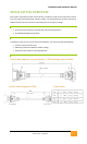
STEP1: DC CONNECTION
IMPORTANT: ALWAYS CONNECT DC FIRST. DO NOT ENERGIZE AC BUS TO
INVERTERS UNTIL ALL INVERTERS HAVE BEEN DC POWERED WITH
ENOUGH SUN LIGHT (LED code continuously blinking)
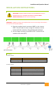
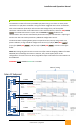
STEP2: AC CONNECTOR – INSTALLATION PROCEDURE
IMPORTANT: all MCB connections must be placed with care not to miss-align. All connectors
are keyed to ensure properly polarity.
1) Place the modular branch connector (MBC) on the inverter
FIRST. This will make it easier to align the small pins on the
inverter with the connector. They self-align and are keyed.
2) Join the larger connector of the MBC to the T-Junction of the
modular trunk cable (MTC).
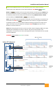
LED CODES
AFTER DC is applied:
Blink Sequence
Meaning
Slow, 1 blink every 4 seconds
DC Connected, NOT Ready for AC to be applied
Continuous Blinking
DC Connected, Ready for AC to be applied (see step 1 warning)
AFTER AC is applied:
Blink Sequence
Meaning
1 blink every 16 seconds
Normal operation, inverter bound to gateway
1 blink every 8 seconds
Normal operation, inverter not bound to gateway
2 blinks every 4 seconds
Inverter phase locked to Grid, no export, no errors
4 blinks every 4 seconds
Error: Grid Voltage out of range
5 blinks every 4 seconds
Error: Panel Voltage out of range