
CP-250E-60/72-208/240-MC4 - User Manual

Installation and Operation Manual
Chilicon Power | Aug 2016
4
IMPORTANT SAFETY INFORMATION
This manual contains important instructions to follow during installation and maintenance of
the Chilicon Power CP-250 microinverter. To reduce the risk of electrical shock and ensure the
safe installation and operation of microinverters, the following symbols appear throughout this
document to indicate dangerous conditions and important safety instructions.
SAVE THESE INSTRUCTIONS – This manual contains important instructions for model CP-250E-
60/72-208/240-MC4 that shall be followed during installation and maintenance of the
microinverter.
WARNING: This indicates a situation where failure to follow instructions
may cause a serious hardware failure or personnel danger if not applied
appropriately. Use extreme caution when performing this task. The CP-
250E microinverter implements and integrated GFDI device that satisfies
Article 690 of the National Electrical Code for ground fault detection. The
integrated ground fault detector requires that the inverter be properly earth grounded using
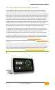
the integrated trunk cable grounding wire. If an inverter is in ground fault, this state is indicated
by the CP-100 gateway device. An inverter in ground fault cannot export power unless the
ground fault detection is specifically bypassed by the installer using a message that is broadcast
to the inverter from the gateway. Chilicon does not recommend bypassing ground fault power
export lock out. However, if this lock out is disabled, the inverter will export power while
continuing to indicate ground fault to the gateway.
Note: There is no galvanic path from the DC to AC connections in the device, or from DC
connectors to the enclosure, or AC connectors to the enclosure. The rated hi-pot on any of
these paths is 2500Vrms.
CAUTION: Risk of electrical shock. Do not remove endplates from device.
No user serviceable parts are inside the inverter. When the photovoltaic
array is exposed to light it supplies a DC voltage to this equipment
WARNING: Electric Shock Hazard. The DC Conductors of this photovoltaic system are
ungrounded and may be energized.
WARNING: Perform all electrical installations in accordance with local electrical codes and with
National Electrical Code, ANSI/NFPA 70, including Sec. 690.35 with an ungrounded PV array.
WARNING: The maximum open circuit voltage of the PV module must not exceed the specified
maximum input voltage of the microinverter (for CP-250E-60/72-208/240-MC4 this is 60 Volts).
WARNING: Verify the voltage and current specifications of your PV module match with those of
the microinverter. All poly and mono-crystalline silicon 60 and 72-cell panels should be
compatible. Do Not connect silicon silicon 96-cell, amorphous, thin-film panels, or other panel
types to CP-250E-60/72-xx microinverters. Connecting any device whose supply exceeds 60VDC
will cause a shutdown of the inverter. Though the device may continue to operate when
returned to normal voltage, the event will be recorded in flash memory and will void the
warranty.