Installation and Operation Manual CP-250E-60/72-208/240-MC4 Microinverter with Modular Trunk Cable Chilicon Power | Aug 2016 1
Installation and Operation Manual CONTENTS CP-250E Microinverter System ....................................................................................................... 3 The CP-100 Cortex Gateway .................................................................................................... 3 Important Safety Information ......................................................................................................... 4 Inverter Label Information ........................................
Installation and Operation Manual CP-250E MICROINVERTER SYSTEM The CP-250E-60/72-MC4 microinverter has been designed ground up for industry leading efficiency (96.6% peak, and 96.09% CEC) and reliability. The devices contain no electrolytic capacitors and no opto-isolators. The chassis uses an aluminum extrusion process optimized for high volume manufacturing and is rated to NEMA-6. This rating allows environmental extremes beyond those found beneath solar panels where the inverters are installed.
Installation and Operation Manual IMPORTANT SAFETY INFORMATION This manual contains important instructions to follow during installation and maintenance of the Chilicon Power CP-250 microinverter. To reduce the risk of electrical shock and ensure the safe installation and operation of microinverters, the following symbols appear throughout this document to indicate dangerous conditions and important safety instructions.
Installation and Operation Manual WARNING: Be aware that the body of the Chilicon Power Microinverter is the heat sink, and although it usually rises less than 20°C above ambient, it can reach a temperature of 80°C. To reduce risk of burns, do not touch the body of the microinverter. WARNING: Do NOT attempt to repair the Chilicon Power Microinverter. If it fails, contact customer support to obtain an RMA number and start the replacement process.
Installation and Operation Manual INSTALLATION OVERVIEW A PV system using Chilicon Power microinverters is simple to install. Each microinverter mounts on the PV racking, directly beneath each PV module. Low voltage DC wires connect from the PV module directly to the microinverter, eliminating the risk of high DC voltage.
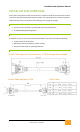
Installation and Operation Manual INSTALLATION INSTRUCTIONS STEP1: DC CONNECTION IMPORTANT: ALWAYS CONNECT DC FIRST. DO NOT ENERGIZE AC BUS TO INVERTERS UNTIL ALL INVERTERS HAVE BEEN DC POWERED WITH ENOUGH SUN LIGHT (LED code continuously blinking) STEP2: AC CONNECTOR – INSTALLATION PROCEDURE IMPORTANT: all MCB connections must be placed with care not to miss-align. All connectors are keyed to ensure properly polarity. 1) Place the modular branch connector (MBC) on the inverter FIRST.
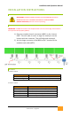
Installation and Operation Manual WIRING FOR COMMUNICATION TO THE GATEWAY (240 V SPLIT-PHASE SYSTEMS) Chilicon Power trunk cables have 4 color-coded conductors: RED, BLACK, BLACK and , GREEN conductors are for the PLC communication. The same grid line (BLACK) must be used to connect the inverter to the Gateway to ensure robust communication. Specifically, the Gateway inside the home (120 V) should be powered using GRID HOT LINE B (= BLACK trunk conductor) and GRID NEUTRAL (= trunk conductor).
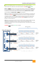
Installation and Operation Manual THREE PHASE 208 VOLT WIRING The maximum number of inverters per 208-V split-phase string is 13. There are three power conductors in a split phase installation. Strings should be staggered across these 3 conductors, with a third conductor (neutral) to reference the mid-voltage of any 2 of the 3 power conductors. Chilicon Power trunk cables have 3 color coded conductors, these are: RED, BLACK, .
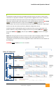
Installation and Operation Manual CABLE MAXIMUMS The maximum size current protection device allowed by NEC code for use with 12AWG wire in the trunk cable is 20A. This leads to the following calculations for the maximum number of allowed inverters per trunk cable. A. Maximum number of inverters on a 20 amp, 240V circuit: 250W output mode: (20A/(1.04*1.25)) = 15 285W output mode: (20A/(1.18*1.25)) = 13 (if 285W enabled by gateway) B.