
User's Manual

PFC Series Installation Instructions
6
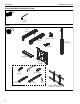
ASSEMBLY
CAUTION: Attachment holes may be damaged if a power
drill is used to insert button head cap screws. Screws should
first be inserted and turned BY HAND with the hex key or with
a handheld screwdriver BEFORE using the hex head drill bit
(H) and power drill to complete the attachment.
Assembling Cart
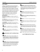
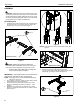
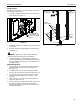
1. Assemble two legs (A) and (B) to the cart cross bracket (F)
using two 5/16-18 x 4-1/2" button head cap screws (M)
through one end cap (C) per leg. (See Figure 1)
Figure 1
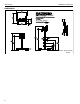
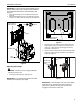
CAUTION: INNER AND OUTER COLUMNS ARE
SHIPPED TAPED TOGETHER. After tape is removed the
inner column will be disengaged and may pinch hands!
• Remove tape while CAREFULLY holding both
inner and outer columns in place.
IMPORTANT ! : Press cable tie tab to loosen and remove
cable tie from around knob post. (See Figure 2)
NOTE:
Disengage knob on center post BEFORE attaching
base to the center post.
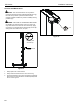
2. Lift up slightly on the inner column of center post and hold
firmly toward top of post. (See Figure 2)
3. Pull out knob on the center post and turn 90° in either
direction to disengage the locking mechanism. (See
Figure 2)
4. Raise the inner column and turn the knob 90° in either
direction to engage the knob and lock the column in place.
(See Figure 2)
Figure 2
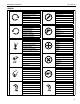
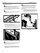
NOTE:
Insert and turn screws in order shown (1, 2, 3, 4) in
Figure 3.
Figure 3
5. Attach center post (E) to leg assembly using four
5/16-18 x 2-3/4" button head cap screws (L) and four 5/16"
washers (N). (See Figure 3) and (See Figure 4)
Figure 4
(Front view of cart)
(M) x 4
(C) x 2
(B)
(F)
(A)
inner column
Cable
Tie
(Bottom view of cart)
1
2
3
4
(Front view of cart)
(L) x 4
(N) x 4
(E)