INSTALLATION INSTRUCTIONS Istruzioni di installazione Installatie-instructies Instructions d´installation Instrucciones de instalación Installationsanleitung Instruções de Instalação K2C120 K2C110 K2C220 K2C120SXF1 K2C220SXF1 K2C22H K2C22HSXF1 K2C Column Mounts Spanish Product Description German Product Description Portuguese Product Description Italian Product Description Dutch Product Description French Product Description K2C Series
K2C Series Installation Instructions DISCLAIMER Milestone AV Technologies and its affiliated corporations and subsidiaries (collectively “Milestone”), intend to make this manual accurate and complete. However, Milestone makes no claim that the information contained herein covers all details, conditions or variations, nor does it provide for every possible contingency in connection with the installation or use of this product.
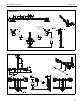
Installation Instructions K2C Series DIMENSIONS K2C110 6.75 171.5 90 TILT RANGE UP 15 DOWN MOUNTING PATTERN COMPATIBILITY 100 X 100 75 X 75 MANUAL HEIGHT ADJUST RANGE DESKTOP THICKNESS RANGE 2.50 0.50 63.5 12.7 3.69 93.7 K2C120 5.17 131.3 6.75 171.5 6.75 171.5 2.32 59.0 INTERFACE ROTATION RANGE 90 TILT RANGE 15 UP 15 DOWN MOUNTING PATTERN COMPATIBILITY 100 X 100 75 X 75 MANUAL HEIGHT ADJUST RANGE 19.26 12.26 489.2 311.4 3.69 93.7 DESKTOP THICKNESS RANGE 2.50 0.50 63.5 12.
K2C Series Installation Instructions K2C220 1.88 47.6 MOUNTING PATTERN COMPATIBILITY 100 X 100 75 X 75 INTERFACE ROTATION RANGE 90 UP 15 DOWN MANUAL HEIGHT ADJUST RANGE 19.24 12.24 488.8 311.0 DESKTOP THICKNESS RANGE 1.50 38.1 K2C120SXF1 2.32 59.0 90 TILT RANGE UP 15 DOWN MOUNTING PATTERN COMPATIBILITY 100 X 100 75 X 75 MANUAL HEIGHT ADJUST RANGE 1.69 43.0 4 1.81 46.
Installation Instructions K2C Series K2C220SXF1 1.88 47.6 MOUNTING PATTERN COMPATIBILITY 100 X 100 75 X 75 INTERFACE ROTATION RANGE 90 UP 15 DOWN 0.18 4.6 MANUAL HEIGHT ADJUST RANGE 19.40 12.40 492.7 314.9 K2C22H 6.75 171.5 INTERFACE ROTATION RANGE 90 MOUNTING PATTERN COMPATIBILITY 100 X 100 75 X 75 UP 10 DOWN 3.69 93.7 ADJUST RANGE DESKTOP THICKNESS RANGE 2.50 0.50 63.5 12.
K2C Series Installation Instructions K2C22HSXF1 6.75 171.5 MOUNTING PATTERN COMPATIBILITY 100 X 100 75 X 75 INTERFACE ROTATION RANGE 90 UP 10 DOWN 1.69 43.0 ADJUST RANGE 3.52 89.
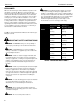
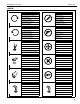
Installation Instructions K2C Series LEGEND Tighten Fastener Pencil Mark Apretar elemento de fijación Marcar con lápiz Befestigungsteil festziehen Stiftmarkierung Apertar fixador Marcar com lápis Serrare il fissaggio Segno a matita Bevestiging vastdraaien Potloodmerkteken Serrez les fixations Marquage au crayon Loosen Fastener Drill Hole Aflojar elemento de fijación Perforar Befestigungsteil lösen Bohrloch Desapertar fixador Fazer furo Allentare il fissaggio Praticare un foro Beves
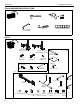
K2C Series Installation Instructions TOOLS REQUIRED FOR INSTALLATION #2 3/16” (included) 1/8” (included) PARTS A (1) [Desk clamp arm] (K2C110 shown) or A (1) [Frame One arm] (K2C120SXF1 shown) included with SXF1 models only K (1) [Channel plate] B (4 or 8)* M4x14mm C (4 or 8)* M4x25mm D (4 or 8)* M10x5.
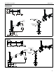
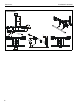
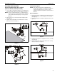
Installation Instructions K2C Series Assembly And Installation Grommet Hole Option Connecting Desk Clamp Arms to Desk (K2C110, K2C120, K2C220, K2C22H) NOTE: K1C clamp mounts may be installed directly to 1. grommet holes between 1 1/4” and 2 1/2” in diameter. If grommet hardware (F-H) is used, they can be installed to grommet holes between 3/8” and 2 1/2” in diameter. Loosen clamp screw until enough space is created between clamp and mount to allow for desk mounting.
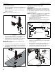
K2C Series Installation Instructions Using Grommet Hardware 1. 2. Remove desk clamp from mount by loosening button head cap screw until clamp is completely disengaged from the bolt. (See Figure 5) Maneuver clamp so that it is totally removed from desk mount. (See Figure 5) NOTE: Set removed washer aside for re-use. Assembly to Office Furniture Rail (SFX1 Models) IMPORTANT ! : The SFX1 models are designed to be installed to Steelcase Frame One™ office furniture rails.
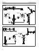
Installation Instructions K2C Series NOTE: If mount leans forward after installation, install one or two shims (L) in between mount base and rail as shown in the following steps. Array Installation (K2C22H and K2C22HSXF1 Models ONLY) 1. Slide rotational spacer (J10) into opening on array attachment bracket. (See Figure 10) IMPORTANT ! : Do NOT install one or both shims (L) unless required as damage to the Frame One rail may result! 2.
K2C Series Installation Instructions Display Installation (non-array versions) Flush Mounting Holes NOTE: K2C22H models have K1 Series faceplates on array arms. Proceed to K2C22H Models Section. CAUTION: Using screws of improper size may damage The mounting holes on the back of the display will either be flush with the back surface or recessed into the back surface. Refer to the applicable installation procedure.
Installation Instructions K2C Series Recessed Mounting Holes K2C22H Models 1. Ensure Centris bracket is able to swivel and tilt easily, yet still be tight enough to hold display in desired position. Adjust as required before proceeding. See “ADJUSTMENT” for detail. 1. 2. Carefully place display face down on protective surface. 3. Place the four spacers (D) over each of the mount holes on the back of the display. (See Figure 12) 4.
K2C Series Installation Instructions For recessed mounting hole installation: Handle Installation (K2C22 models only) • 1. Loosen four screws securing handle brackets to K1C22H array. (See Figure 17) 2. Install uprights of handle (J) into handle brackets located on the back of K1C22 array. (See Figure 17) • Place four spacers (D) on top of mounting holes on back of display.
Installation Instructions K2C Series Adjustments Adjustments - K2C22H models only Portrait Adjustment (K2C22H Models only) 1. Loosen knobs securing faceplates to array. (See Figure 21) 1. The monitor may be adjusted 90 degrees in either direction in order to provide a portrait view of the monitor. (See Figure 19) 2. Slide displays laterally on array to adjust lateral shift. (See Figure 21) 3. Adjust pitch and pivot position as desired. (See Figure 21) 2.
K2C Series Installation Instructions Pivot Adjustment Range Swing Arm Pivot Adjustment Single Arm Models 1. Adjust pivot position as desired. (See Figure 25) 1. 2. Adjust pivot point tension screws to change pivot adjustment tension. (See Figure 25) Adjust arm angle as desired up to 90 degrees in either direction.
Installation Instructions K2C Series Array Models 1. Install cable clips (J7) to back of array. (See Figure 27) 2. Route cables through cable clips (J7) as desired.
K2C Series 18 Installation Instructions
Installation Instructions K2C Series 19
K2C Series Installation Instructions USA/International Europe Chief, a products division of Milestone AV Technologies 8800-002481 Rev00 2014 Milestone AV Technologies www.chiefmfg.com 03/14 Asia Pacific A P F A P F A 6436 City West Parkway, Eden Prairie, MN 55344 800.582.6480 / 952.225.6000 877.894.6918 / 952.894.6918 Franklinstraat 14, 6003 DK Weert, Netherlands +31 (0) 495 580 852 +31 (0) 495 580 845 Office No.