INSTALLATION INSTRUCTIONS Instrucciones de instalación Installationsanleitung Instruções de Instalação K1C110 K1C120 Istruzioni di installazione Installatie-instructies Instructions d´installation K1C120BI2 K1C210 K1C120SXF1 K1C220SXF1 K1C220 K1C210SXF1 K1C22H K1C22HSXF1 K1 Column Mounts Spanish Product Description German Product Description Portuguese Product Description Italian Product Description Dutch Product Description French Product Description K1C Series
K1C Series Installation Instructions DISCLAIMER Milestone AV Technologies and its affiliated corporations and subsidiaries (collectively “Milestone”), intend to make this manual accurate and complete. However, Milestone makes no claim that the information contained herein covers all details, conditions or variations, nor does it provide for every possible contingency in connection with the installation or use of this product.
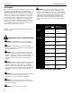
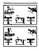
Installation Instructions K1C Series DIMENSIONS K1C110 5.17 131.3 FULL UP/DOWN = MIN TILT RANGE UP 10 DOWN RANGE 90 MOUNTING PATTERN COMPATIBILITY 100 X 100 75 X 75 HEIGHT ADJUST RANGE MANUAL (7") + DYNAMIC (13") 23.77 3.77 603.8 95.8 DESKTOP THICKNESS RANGE 3.69 93.7 K1C120 1.83 46.4 90 TILT RANGE UP 10 DOWN MOUNTING PATTERN COMPATIBILITY 100 X 100 75 X 75 HEIGHT ADJUST RANGE MANUAL (7") + DYNAMIC (13") 32.75 12.75 831.7 323.7 3.69 93.7 DESKTOP THICKNESS RANGE 2.50 0.50 63.5 12.
K1C Series Installation Instructions K1C120BXI2 1.83 46.4 TILT RANGE UP 10 DOWN 90 HEIGHT ADJUST RANGE MANUAL (7") + DYNAMIC (13") 3.69 93.7 MOUNTING PATTERN COMPATIBILITY 100 X 100 75 X 75 DESKTOP THICKNESS RANGE 2.50 0.50 63.5 12.7 K1C120SXF1 FULL UP/DOWN = MIN 1.83 46.4 TILT RANGE UP 10 DOWN 90 HEIGHT ADJUST RANGE MANUAL (7") + DYNAMIC (13") 31.69 11.65 805.0 296.0 1.69 43.
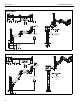
Installation Instructions K1C210 DYNAMIC LIFT ARM LENGTH RANGE STRAIGHT = MAX FULL UP/DOWN = MIN 10.21 7.12 259.3 180.9 INTERFACE ROTATION RANGE 90 K1C Series 1.88 47.6 1.81 46.0 MOUNTING PATTERN COMPATIBILITY 100 X 100 75 X 75 UP 10 DOWN HEIGHT ADJUST RANGE MANUAL (7") + DYNAMIC (13") 23.02 3.02 584.7 76.7 DESKTOP THICKNESS RANGE 2.50 0.50 63.5 12.7 K1C220 1.88 47.6 FULL UP/DOWN = MIN 1.81 46.
K1C Series Installation Instructions K1C210SFX1 DYNAMIC LIFT ARM LENGTH RANGE STRAIGHT = MAX FULL UP/DOWN = MIN 10.21 7.12 259.3 180.9 INTERFACE ROTATION RANGE 90 1.88 47.6 MOUNTING PATTERN COMPATIBILITY 100 X 100 75 X 75 UP 10 DOWN HEIGHT ADJUST RANGE MANUAL (7") + DYNAMIC (13") 21.96 1.92 557.8 48.7 0.18 4.6 K1C220SXF1 1.88 47.6 FULL UP/DOWN = MIN INTERFACE ROTATION RANGE 90 MOUNTING PATTERN COMPATIBILITY 100 X 100 75 X 75 UP 10 DOWN HEIGHT ADJUST RANGE MANUAL (7") + DYNAMIC (13") 30.28 11.
Installation Instructions K1C Series K1C22H DYNAMIC LIFT ARM LENGTH RANGE STRAIGHT ARM = MAX FULL UP/DOWN = MIN 10.21 7.12 259.3 180.9 6.75 171.5 INTERFACE ROTATION RANGE 90 MOUNTING PATTERN COMPATIBILITY 100 X 100 75 X 75 UP 10 DOWN 3.69 93.7 MANUAL (7") + DYNAMIC (13") DESKTOP THICKNESS RANGE 2.50 0.50 63.5 12.7 K1C22HSXF1 6.75 171.5 DYNAMIC LIT ARM LENGTH RANGE STRAIGHT = MAX FULL UP/DOWN = MIN 10.21 7.12 259.3 180.
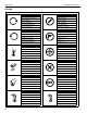
K1C Series Installation Instructions LEGEND 8 Tighten Fastener Pencil Mark Apretar elemento de fijación Marcar con lápiz Befestigungsteil festziehen Stiftmarkierung Apertar fixador Marcar com lápis Serrare il fissaggio Segno a matita Bevestiging vastdraaien Potloodmerkteken Serrez les fixations Marquage au crayon Loosen Fastener Drill Hole Aflojar elemento de fijación Perforar Befestigungsteil lösen Bohrloch Desapertar fixador Fazer furo Allentare il fissaggio Praticare un foro B
Installation Instructions K1C Series TOOLS REQUIRED FOR INSTALLATION #2 3/16” (included) 1/8” (included) PARTS E (1) [iPad® interface - iPad versions only! + A (1) [Desk clamp arm] (K1C110 shown) * - (single display models/dual display models) or A (1) [Frame One arm] (K1C120SXF11 shown) I2B Interface +installation manual B (4/8)* M4x14mm C (4/8)* M4x25mm Grommet Hardware (included with clamp models only) F (2) [Clamp bracket] G (1) 5/16-18” included with SXF1 models only D (4/8)* M10x5.
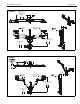
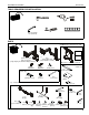
K1C Series Installation Instructions Assembly And Installation Grommet Hole Option Connecting Desk Clamp Arms to Desk (K1C100, K1C120, K1C120BI2) Standard Installation NOTE: K1C clamp mounts may be installed directly to 1. Loosen clamp screw until enough space is created between clamp and mount to allow for desk mounting. (See Figure 1) NOTE: If space is limited behind desk (i.e. against wall, etc.
Installation Instructions K1C Series Using Grommet Hardware 1. 2. Remove desk clamp from mount by loosening button head cap screw until clamp is completely disengaged from the bolt. (See Figure 5) Maneuver clamp so that it is totally removed from desk mount. (See Figure 5) NOTE: Set removed washer aside for re-use. Assembly to Office Furniture Rail (SFX1 Models) IMPORTANT ! : The SFX1 models are designed to be installed to Steelcase FrameOne™ office furniture rails.
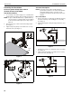
K1C Series Installation Instructions Installing Shim Spacers (if required) IMPORTANT ! : Do NOT install one or both shims (M) unless required as damage to the FrameOne ™ rail may result! 6. Remove two #10-32 x 7/8” flat head cap screws (N) holding mount base to channel plate (L). 7. Slide one or two shims (M) in between mount base and rail, lining up holes on shim(s) with holes on plate and rail. (See Figure 9) 8.
Installation Instructions K1C Series Display Installation MODEL Max Weight Allowed for EACH Display Max Weight Capacity of Mounting System K1C220SXF1 22 lbs 44 lbs (9.98 kg) (19.96 kg) 9 lbs 18 lbs (4.08 kg) (8.16 kg) 9 lbs 18 lbs (4.08 kg) (8.16 kg) NOTE: For K1C120BXI2 mounts, refer to FSBI2B installation instructions to install iPad® to mounting arm. 1. Remove quick release faceplate from mount by pulling quick release lever and sliding faceplate off mount.
K1C Series Installation Instructions For recessed mounting hole installation: Handle Installation (K1C22H models only) • 1. Loosen four screws securing handle brackets to K1C22H array. (See Figure 15) 2. Install uprights of handle (J) into handle brackets located on the back of K1C22 array. (See Figure 15) • Place four spacers (D) on top of mounting holes on back of display.
Installation Instructions K1C Series Adjustments 6. Pitch Adjustment (non-array models) Lift Arm Tension Adjustment 1. Adjust pitch to desired tilt position. (See Figure 17) 1. 2. Adjust pitch tension screw to change the adjustment tension. (See Figure 17) Use 3/16” hex key (P) to adjust rotational adjustment screw to adjust rotational tension. (See Figure 17) Use 3/16” hex key (P) to adjust lift arm tension adjustment screw. (See Figure 19) Pivot Adjustment (non-array models) 3.
K1C Series Installation Instructions Adjustments - K1C22H models only Display Adjustments 1. Loosen knobs securing faceplates to array. (See Figure 22) 2. Slide displays laterally on array to adjust lateral shift. (See Figure 22) 3. Adjust pitch and pivot position as desired. (See Figure 22) 4. Tighten knobs to secure faceplates in position.
Installation Instructions K1C Series Pivot Adjustment Range Cable Management Single Arm Models 1. Press insides of cable management covers at both ends to unhinge tabs on either end of cable management cover on upper arm. (See Figure 26) 2. Lift cable management cover up until tabs are unhinged and cover is in the “open” position. (See Figure 26) 1. Adjust arm angle as desired up to 90 degrees in either direction.
K1C Series Installation Instructions Array Models 1. Install array cable clips (J7) to back of array. (See Figure 28) 2. Route cables through array cable clips (J7) as desired. (See Figure 28) 3. Route cables through arm cable clips as desired.
Installation Instructions K1C Series 19
K1C Series Installation Instructions USA/International Europe Chief, a products division of Milestone AV Technologies 8800-002477 Rev01 2014 Milestone AV Technologies www.chiefmfg.com 06/14 Asia Pacific A P F A P F A 6436 City West Parkway, Eden Prairie, MN 55344 800.582.6480 / 952.225.6000 877.894.6918 / 952.894.6918 Franklinstraat 14, 6003 DK Weert, Netherlands +31 (0) 495 580 852 +31 (0) 495 580 845 Office No.