
User's Manual


VT-M2M-TC VM
All Rights Reserved
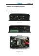
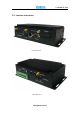
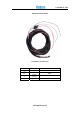
3.5.2 SmartDisplayConnector
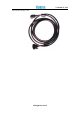
Smart Display Connector Photo
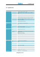
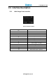
Pin Definition of Smart Display Connector
Pin Description Pin Description
1 LCD_BL_EN( Backlight Enable output) 19 USB_D-(USB Data Negative Output Pin)
2
Panel_PWR_EN(Panel Power Enable
output)
20 USB_D+(USB Data Positive Output Pin)
3 LVDS Ground(ground pin) 21 USB Ground(ground pin)
4 Reset_BTN#(Reset Signal Input) 22 USB Ground(ground pin)
5
LVDS_CLKP(Positive Clock Signal Input
Pin)
23 +12 VDC output(+/- 10%, max 1.5A)
6
LVDS_CLKN( Negative Clock Signal Input
Pin)
24 +12 VDC output(+/- 10%, max 1.5A)
7 LVDS Ground(ground pin) 25 +12 VDC output(+/- 10%, max 1.5A)
8 LVDS Ground(ground pin) 26 +12 VDC output(+/- 10%, max 1.5A)
9
LVDS_DATAP2(LVDS Data2 Positive Input
Pin)
27 Power Ground(ground pin)
10
LVDS_DATAN2(LVDS Data2 Negative
Input Pin)
28 Power Ground(ground pin)
11 RS232_TXD1(RS232 Data output Pin) 29 Power Ground(ground pin)
12 RS232_RXD1(RS232 Data input Pin) 30 Power Ground(ground pin)
13
LVDS_DATAP1(LVDS Data1 Positive Input
Pin)
31 N/C(Not Connect)
14
VDS_DATAN1(LVDS Data1 Negative
Input Pin)
32 N/C(Not Connect)
15 LVDS Ground(ground pin) 33 N/C(Not Connect)
16 LVDS Ground(ground pin) 34 Power Button Input #
17
VDS_DATAP0(LVDS Data0 Positive Input
Pin)
35 Audio Ground
18
VDS_DATAN0(LVDS Data0 Negative
Input Pin)
36 Mono. Line-out( left channel)