
User's Manual


All rights reserved Page 9, Total 13
4 Hardware Description
This chapter describe the hardware Features include, switch, jumper, connector and PIN
function
The interface description ought to consult the connector sketch map. And attach
necessary message such as picture. Indicate the figure, PIN1 and match jack
4.1 Identify connector
This section describe how to find the position of connector and PIN1 on AV 7
single computer board.
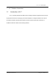
4.1.1 Position of connector
As Figure 4.2show the main part and connector position of AV 7.
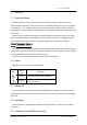
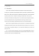
4.1.2 Confirm the pin direction
there is the pin number order in all Vantron’s
product, this picture at right indicate each pin’s
number, that message as show on the top
side(component side) of main board. on double row
connector, one side is naming odd number and another
side is naming even number. Please according to below method to confirm the Pin1 of
connector and jumper:
1. Usually, there is any number and mark at side of connector in main board, such as
trigonal mark, dot and number “1” all indicate the pin1 of connector
2. About the hole connector, you can see pin number on the reversed side
3.
Download the AV 7 mechanism from Vantron technology sustain or Vantron net
site: www.vantrontech.com
4.2 Connectors Description
This table is the respective describe valid signal of connector on AV 7 board.
Figure type:
N/C Not connect
GND Ground
/ active low signal
+ Positive of difference signal
- negative of difference signal
Signal type:
I Input
O Output
IO input/output
AV 7 User’s Manual (HW)