LED Board 80H033215-005 ver. A0~A2 User’s Manual CHENBRO LED Board User’s Manual 80H033215-005 May / 26 / 2008 15Fl., No.150, Jian Yi Road, Chung Ho City, Taipei Hsien, Taiwan R.O.C., Tel: +886 2 82265500 Fax: +886 2 82265392 Email: info@chenbro.com.tw 1 w w w . c h e n b r o .
LED Board 80H033215-005 ver. A0~A2 User’s Manual Copyright Copyright © 2006 Chenbro Micom Co., Ltd.. All rights reserved. Unless otherwise indicated, all materials in this manual are copyrighted by Chenbro Micom Co., Ltd.. All rights reserved. No part of this manual, either text or image may be used for any purpose other than internal use within purchasing company.
LED Board 80H033215-005 ver. A0~A2 User’s Manual Contents Copyright......................................................................................................................................................2 Technical Support......................................................................................................................................2 Contents ..................................................................................................................................
LED Board 80H033215-005 ver. A0~A2 User’s Manual Revision History Date May / 28 / 2008 Modifications z First release w w w . c h e n b r o . c o m 15Fl., No.150, Jian Yi Road, Chung Ho City, Taipei Hsien, Taiwan R.O.C., Tel: +886 2 82265500 Fax: +886 2 82265392 Email: info@chenbro.com.
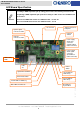
LED Board 80H033215-005 ver. A0~A2 User’s Manual Hardware Specification Specification LED indicates HDD status (Defined by Chenbro) Power LED – Blue ( When HDD is present ) Display Access LED –Green (When HDD is busy ) Error indicator – Red (Error when retreating signals ) Alarm Buzzer & LED (Red) Backplane signal connector Motherboard signal connector Motherboard USB 2.0 connector External USB 2.
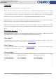
LED Board 80H033215-005 ver. A0~A2 User’s Manual LED Board Specification According to HDD sequential spin up setting, please refer to the following instruction. The text printing of HDD sequential spin up function setting on older version 1U~5U LED boards are incorrect. The incorrect LED board version are: 80H033215-005 ver. A0~A2 The corrected LED board version are: 80H033215-005 ver. A3 I2C connector Signal connector to backplane System signal connector to M/B Function Switch USB 2.
LED Board 80H033215-005 ver.
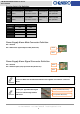
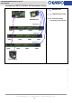
LED Board 80H033215-005 ver. A0~A2 User’s Manual Chassis Assembly Example Example for RM21508B Mini-SAS backplane wiring Mini-SAS cable LED board signal cable LED Board HBA / RAID Card Chassis fan wiring (Connecting start from Fan1) CN4 jumper set on pins 3 & 4 HDD8 HDD7 HDD6 HDD5 CN4 jumper set on pins 1 & 2 HDD4 HDD3 HDD2 HDD1 Chassis Fan x4 w w w . c h e n b r o . c o m 15Fl., No.150, Jian Yi Road, Chung Ho City, Taipei Hsien, Taiwan R.O.C.
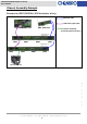
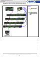
LED Board 80H033215-005 ver. A0~A2 User’s Manual Example for RM31212B Mini-SAS backplane wiring Mini-SAS cable LED board signal cable LED Board HBA/RAID Card Chassis fan wiring (Connecting start from Fan1) CN4 jumper set on pins 5 & 6 HDD12 HDD11 HDD10 HDD9 CN4 jumper set on pins 3 & 4 HDD8 HDD7 HDD6 HDD5 CN4 jumper set on pins 1 & 2 HDD4 HDD3 HDD2 HDD1 Chassis Fan x4 w w w . c h e n b r o . c o m 15Fl., No.150, Jian Yi Road, Chung Ho City, Taipei Hsien, Taiwan R.O.C.
LED Board 80H033215-005 ver. A0~A2 User’s Manual Example for RM41416B Mini-SAS backplane wiring Mini-SAS cable LED board signal cable LED Board HBA/RAID Card Chassis fan wiring CN4 jumper set on pins 7 & 8 (Connecting start from Fan1) HDD16 HDD15 HDD14 HDD13 CN4 jumper set on pins 5 & 6 HDD12 HDD11 HDD10 HDD9 CN4 jumper set on pins 3 & 4 HDD8 HDD7 HDD6 HDD5 CN4 jumper set on pins 1 & 2 HDD4 HDD3 HDD2 HDD1 Chassis Fan x5 w w w . c h e n b r o . c o m 15Fl., No.