
User guide

6
LED Board 80H033215-003 ver. 1.1~1.2
User’s Manual
15Fl., No.150, Jian Yi Road, Chung Ho City, Taipei Hsien, Taiwan R.O.C.,
Tel: +886 2 82265500 Fax: +886 2 82265392 Email: info@chenbro.com.tw
www.chenbro.com
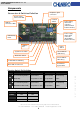
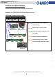
Components
Connectors & Switches Definition
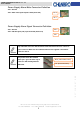
Function Switch Pin Definition
SW 1 SW 2 SW 3 SW 4
ON
Fan1~5 Monitoring Enable
(RM41616B)
System Alarm
Temperature is 65°C
HDD Sequential
Spin up Disable
Fan Monitoring
Enable
OFF
Fan1~4 Monitoring Enable
(RM21508B & RM31212B)
System Alarm
Temperature is 55°C
HDD Sequential
Spin up Enable
Fan Monitoring
Disable
SW 5 SW 6
8 HDDs
OFF OFF
12 HDDs
ON OFF
16 HDDs
OFF ON
USB 2.0
Port
Yellow LED on: HDD busy
System Reset Switch
Alarm Mute Switch
Red LED on:
System Error
Power
Switch
Green LED On:
LAN 1 Busy
Green LED On:
LAN 2 Bus
y
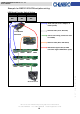
Power supply
alarm signal
connector
(Red & Black
Cable from PSU)
Power supply
alarm mute
connector
(Yellow & Black
Cable from PSU)
Backplane signal
connectors
System signal
connector to M/B
USB 2.0
connector to M/B
Function
Switch
HDD Activity
LEDs
Blue LED on: Power On