LED Board 80H033215-003 ver. 1.1~1.2 User’s Manual CHENBRO LED Board User’s Manual Version 1.1~1.2 May / 26 / 2008 15Fl., No.150, Jian Yi Road, Chung Ho City, Taipei Hsien, Taiwan R.O.C., Tel: +886 2 82265500 Fax: +886 2 82265392 Email: info@chenbro.com.tw 1 w w w . c h e n b r o .
LED Board 80H033215-003 ver. 1.1~1.2 User’s Manual Copyright Copyright © 2006 Chenbro Micom Co., Ltd.. All rights reserved. Unless otherwise indicated, all materials in this manual are copyrighted by Chenbro Micom Co., Ltd.. All rights reserved. No part of this manual, either text or image may be used for any purpose other than internal use within purchasing company.
LED Board 80H033215-003 ver. 1.1~1.2 User’s Manual Contents Copyright ..................................................................................................................................................... 2 Technical Support ..................................................................................................................................... 2 Contents...............................................................................................................................
LED Board 80H033215-003 ver. 1.1~1.2 User’s Manual Revision History Date May / 26 / 2008 Modifications z First Release w w w . c h e n b r o . c o m 15Fl., No.150, Jian Yi Road, Chung Ho City, Taipei Hsien, Taiwan R.O.C., Tel: +886 2 82265500 Fax: +886 2 82265392 Email: info@chenbro.com.
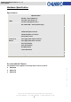
LED Board 80H033215-003 ver. 1.1~1.2 User’s Manual Hardware Specification Specification Specification HDD LED – Yellow (HDD busy) Display Power LED – Blue (Power on) Error LED – Red (System error ) LAN1, LAN2 LEDs – Green (Internet busy) Alarm Buzzer & LED (Red) Backplane signal connector Motherboard signal connector Motherboard USB 2.0 connector External USB 2.
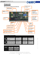
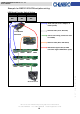
LED Board 80H033215-003 ver. 1.1~1.2 User’s Manual Components Connectors & Switches Definition Backplane signal connectors System signal connector to M/B Function Switch USB 2.0 connector to M/B Power supply alarm mute connector (Yellow & Black Cable from PSU) Power supply alarm signal connector (Red & Black Cable from PSU) HDD Activity LEDs USB 2.
LED Board 80H033215-003 ver. 1.1~1.2 User’s Manual Power Supply Alarm Mute Connector Definition Pin 1: Ground Pin 2: Alarm mute signal output to PSU (Active low) Pin 2 Pin 1 Power Supply Alarm Signal Connector Definition Pin 1: Ground Pin 2 Pin 2: PSU fail signal (TTL) input from PSU (Active low) Pin 1 Only redundant PSU come with the failure alarm and alarm mute reset control via signal connector. Make sure the redundant PSU that user applied come with the connectors above.
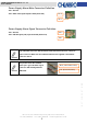
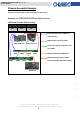
LED Board 80H033215-003 ver. 1.1~1.2 User’s Manual Backplane and LED Board Wiring 1. Use 4 pcs of SATA-II cable per backplane for HOST to Backplane connection. 2. For the Fan connectors, connect the system middle Fan (3P3C) to the Backplane. 3. For the Fail LED output, connect the attached cable from RAID card (only if failure LED output is supported) to Backplane (CN2). 15Fl., No.150, Jian Yi Road, Chung Ho City, Taipei Hsien, Taiwan R.O.C., Tel: +886 2 82265500 Fax: +886 2 82265392 Email: info@chenbro.
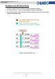
LED Board 80H033215-003 ver. 1.1~1.2 User’s Manual Chassis Assembly Example See below for the example of how the wiring to be performed.
LED Board 80H033215-003 ver. 1.1~1.
LED Board 80H033215-003 ver. 1.1~1.